
BPi-CAN

About the BPi-CAN PCB
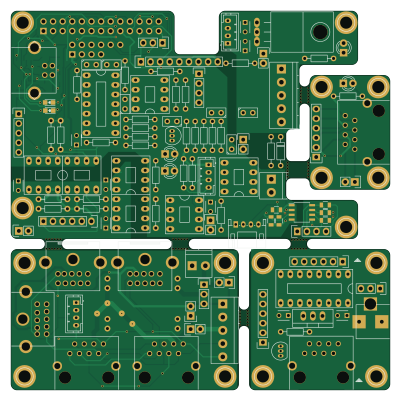
BPi-CAN is an open source PIC PCB design by GBert, published on GitHub. It is a 2-layer board measuring 100 × 100 mm, with 146 components from 89 distinct parts.
Its main chip is the PIC16F15325, from the PIC family. Other key parts include the LM7805, SN65HVD230, PIC18F25K80, 6N137 and TPS5430DDA. By type, the board carries 50 resistors, 41 connectors, 24 capacitors, 14 ICs, 7 diodes and 2 transistors.
From the project
miscellaneous stuff / unsorted
BPI-Model-Railroad-Interface ============================
This is the hardware part of the BPi Railroad Interface:
- CAN - I2C - RS232 Console - RS232 - RS485 - Sniffer input - S88 - SPI for display
Links ----- http://mikrocontroller.bplaced.net/wordpress/?page_id=3071
Main components on the BPi-CAN
BPi-CAN bill of materials (BOM)
146 components, 89 distinct parts — part numbers from the project's BOM.
| Qty | Part | Footprint | Refs |
|---|---|---|---|
| 1 | PIC16F15325 | dil_14-300_socket | U1 |
| 1 | LM7805 | TO-220-78xx | U2 |
| 1 | SN65HVD230 6N137 | dil_8-300_socket | U3 |
| 1 | PIC18F25K80 6N137 | dil_8-300_socket | U4 |
| 3 | 6N137 | dil_8-300_socket | U5, U6, U11 |
| 1 | TPS5430DDA ADuM1251BR | SOIC-8_3.9x4.9mm_Pitch1.27mm | U7 |
| 1 | CD4504 MAX3072E | dil_8-300_socket | U8 |
| 1 | ISO1050 | mdip_8 | U12 |
| 1 | FT230XS | ssop-16 | U13 |
| 1 | LM393 | dil_8-300_socket | U41 |
| 1 | LM7805 | TO-220_Neutral123_Vertical | U71 |
| 1 | 4504 | dil_16-300_socket | U72 |
| 1 | BC337 | TO-92_Inline_Narrow_Oval | Q41 |
| 1 | BC547 | TO-92_Inline_Narrow_Oval | Q71 |
| 1 | BARREL_JACK | BARREL_JACK | CON71 |
| 4 | RJ45 | megb8-8 | J1, J2, J3, J5 |
| 1 | BPi | Socket_Strip_Straight_2x13 | P1 |
| 3 | S88 | Pin_Header_Straight_1x06 | P2, P6, P22 |
| 1 | CONN_02X04 | Socket_Strip_Straight_2x04 | P3 |
| 1 | BPi Con | Socket_Strip_Straight_1x02 | P4 |
Show 69 more
| Qty | Part | Footprint | Refs |
|---|---|---|---|
| 2 | CAN | b4b-ph-kl | P5, P20 |
| 1 | I2C-Bus | Pin_Header_Straight_1x04 | P7 |
| 1 | CAN | pt_1,5-4-3,5-h | P8 |
| 1 | SPI | Pin_Header_Straight_1x09 | P10 |
| 1 | SNIFFER | pt_1,5-2-3,5-h | P11 |
| 2 | CAN-Bus | pt_1,5-5-3,5-h | P12, P14 |
| 1 | USB | conn_usb_B | P13 |
| 1 | POWER | pt_1,5-2-3,5-h | P15 |
| 3 | CAN | minidin-10 | P16, P17, P18 |
| 2 | TERM | Pin_Header_Straight_1x02 | P19, P62 |
| 1 | RS232 Con | Pin_Header_Straight_1x03 | P21 |
| 1 | CONN_01X08 | DCDC | P23 |
| 1 | CONN_01X03 | Pin_Header_Straight_1x03 | P24 |
| 1 | I2C-Bus | Connectors_JST_S4B-PH-K | P25 |
| 2 | CONN_01X02 | Pin_Header_Straight_1x02 | P26, P30 |
| 3 | POWER | Pin_Header_Straight_1x02 | P27, P28, P29 |
| 1 | CONN_01X04 | Pin_Header_Straight_1x04 | P31 |
| 1 | CONN_01X06 | Pin_Header_Straight_1x06 | P32 |
| 1 | CONN_01X05 | Pin_Header_Straight_1x05 | P33 |
| 1 | Loconet | Pin_Header_Straight_1x02 | P41 |
| 1 | RS485 | b4b-ph-kl | P61 |
| 1 | VSELECT | Pin_Header_Straight_1x03 | P71 |
| 6 | abort edge | abort edge | E01, E02, E03, E04, E05, E06 |
| 1 | Ferrit | R_0805_HandSoldering_II | F1 |
| 1 | 1pin | 1pin | RR08 |
| 1 | 1N4148 | diode_do35 | D1 |
| 2 | LED | LED-0805 | D2, D3 |
| 4 | LED | LED-3MM | D5, D6, D41, D42 |
| 2 | 18PF 100nF | C_Disc_D3_P2.5 | C3, C4 |
| 1 | 10UF 100nF | C_Disc_D3_P2.5 | C5 |
| 3 | 100NF 100nF | C_Disc_D3_P2.5 | C6, C8, C11 |
| 3 | 100nF | C_Disc_D3_P2.5 | C7, C71, C72 |
| 2 | 100NF 100nF | R_0805_HandSoldering_II | C9, C10 |
| 2 | 100nF | R_0805_HandSoldering_II | C20, C25 |
| 1 | 10nF | R_0805_HandSoldering_II | C22 |
| 2 | 47pf | R_0805_HandSoldering_II | C23, C24 |
| 1 | 4.7uF | R_0805_HandSoldering_II | C26 |
| 5 | 100nF | cnp_3mm_disc | C27, C28, C31, C42, C44 |
| 1 | 47pF | cnp_3mm_disc | C41 |
| 1 | 1nF | cnp_3mm_disc | C43 |
| 11 | 1pin | 1pin | R01, R02, R03, R04, R05, R06, R07, R08 +3 |
| 2 | 680 270 | RC03 | R2, R3 |
| 1 | 4K7 270 | RC03 | R4 |
| 1 | 680 390 | RC03 | R5 |
| 1 | 3K3 330 | RC03 | R6 |
| 4 | 3K3 1k5 | RC03 | R7, R9, R10, R15 |
| 1 | 1k5 | RC03 | R8 |
| 1 | 270 220 | RC03 | R12 |
| 1 | 1k | RC03 | R13 |
| 1 | 3K3 8k2 | RC03 | R14 |
| 1 | 270 27 | R_0805_HandSoldering_II | R16 |
| 1 | 49.9 27 | R_0805_HandSoldering_II | R17 |
| 2 | 49.9 220 | R_0805_HandSoldering_II | R18, R19 |
| 1 | 1K5 3K3 | R_0805_HandSoldering_II | R24 |
| 1 | 47K 3k3 | R_0805_HandSoldering_II | R25 |
| 1 | 240 3k3 | R_0805_HandSoldering_II | R26 |
| 1 | 2K2 3k3 | R_0805_HandSoldering_II | R27 |
| 1 | 39K 120 | RC03 | R28 |
| 2 | 4k7 | RC03 | R31, R71 |
| 2 | 12 | RC03 | R41, R42 |
| 1 | 47k | RC03 | R43 |
| 1 | 150k | RC03 | R44 |
| 1 | 27k | RC03 | R45 |
| 1 | 39k | RC03 | R46 |
| 1 | 1k8 | RC03 | R47 |
| 1 | 240k | RC03 | R48 |
| 1 | 10k | RC03 | R49 |
| 5 | 470 | RC03 | R50, R51, R52, R61, R62 |
| 1 | 120 | RC03 | R63 |
BPi-CAN design files
The KiCad project lives in the GBert/misc repository on GitHub; these links point at the commit this page was built from.
BPi-CAN: common questions
What microcontroller does the BPi-CAN use?
The BPi-CAN is built around the PIC16F15325, from the PIC family.
How big is the BPi-CAN PCB?
The BPi-CAN measures 100 × 100 mm, has 2 copper layers and is 1.6 mm thick.
How many components are on the BPi-CAN?
146 components, from 89 distinct parts, with part numbers taken from the project's own BOM. The full bill of materials is listed on this page.
Where can I download the BPi-CAN design files?
From the GBert/misc repository on GitHub, which has the KiCad layout and the BOM; the links under Design files point to each one.
Can I use the BPi-CAN design in my own project?
The repository has no license, so all rights stay with GBert. Use it as a reference, and ask the author before reusing the design.
Can I test firmware for the BPi-CAN without the hardware?
Yes. HardLabs builds a simulation of the board from its netlist and BOM, so you can run and debug PIC firmware against it before you order a PCB.
More boards in misc
 PIC
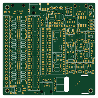
PICCANBuster
100 × 100 mm177 parts2LNo license99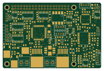 PIC
PICAll in One Railroad Interface
85 × 56.5 mm151 parts2LNo license99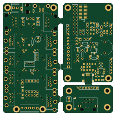
BPI-AddOn
100 × 100 mm94 parts2LNo license99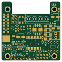 PIC
PICMfx link2
50 × 50 mm61 parts2LNo license99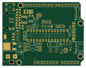 PIC
PICDsPIC33-Arduino
68.6 × 53.3 mm60 parts2LNo license99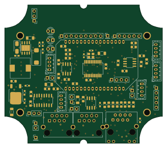 PIC
PICSmallest Rocrail Server Ever II
82 × 72 mm58 parts2LNo license99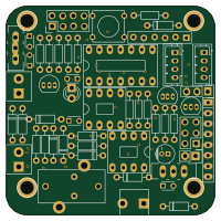 PIC
PICMfx link
50 × 50 mm53 parts2LNo license99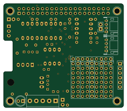
RPi-MCP2515
65 × 56.5 mm42 parts2LNo license99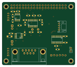 PIC
PICRPi-MCP2517
65 × 56.5 mm35 parts2LNo license99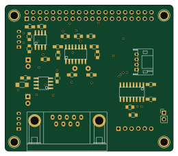 PIC
PICRPi-Rail
65 × 56.5 mm35 parts2LNo license99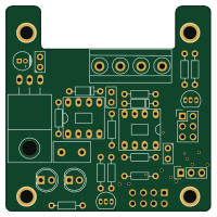
Booster-Link
50 × 50 mm28 parts2LNo license99
Similar boards
 PIC
PICPslab hardware
fossasia
99 × 53.3 mm187 parts4LApache-2.01.7k PIC
PICMicro 8088
skiselev
152.4 × 101.6 mm71 partsGPL-3.0414 PIC
PICGB-CARTPP-DIY
Gekkio
100 × 100 mm22 parts2LCC-BY-4.0376 PIC
PICGB-MBCTEST
51.4 × 61 mm32 parts2LCC-BY-4.0376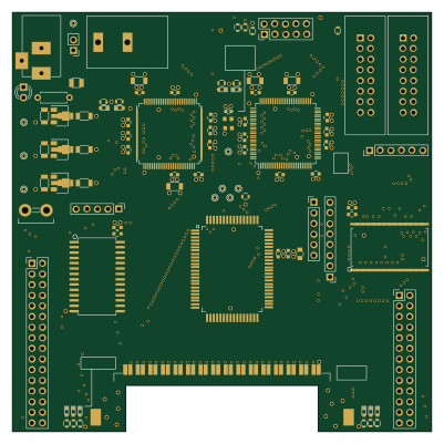 PIC
PICGB-BENCH-G1
100 × 100 mm98 parts4LCC-BY-4.0376 PIC
PICGB-LIVE32
51.4 × 61 mm46 parts4LCC-BY-4.0376