
Z80ROMlessSBC

About the Z80ROMlessSBC PCB
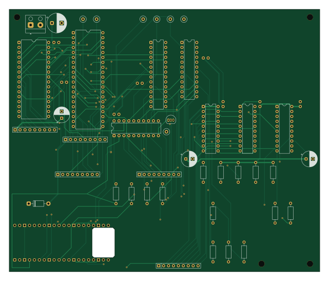
Z80ROMlessSBC is an open source RP2040/RP2350 PCB design by gloveboxes, published on GitHub under the MIT license. It is a 4-layer board measuring 160 × 135 mm, with 51 components from 26 distinct parts.
Its main chip is the Raspberry Pi Pico 2 W, from the RP2040/RP2350 family. Other key parts include the Z84C0020PEC, AS6C1008-55PCN, ATF22V10B/C, SN74AHCT244N and SN74LVC244AN. By type, the board carries 20 resistors, 12 capacitors, 8 ICs, 7 test points, 1 module and 1 transistor.
It belongs with the retro computing designs in this gallery.
From the project
This directory contains the KiCad 10 schematic and the routed four-layer PCB. The board is 160 x 135 mm and uses socket-compatible through-hole footprints. The Pico 2 W is horizontal in the bottom-left corner with USB flush to the left edge; its antenna sits above a dedicated int
This directory contains the KiCad 10 schematic and the routed four-layer PCB. The board is 160 x 135 mm and uses socket-compatible through-hole footprints. The Pico 2 W is horizontal in the bottom-left corner with USB flush to the left edge; its antenna sits above a dedicated internal FR-4/copper cutout.
This is a separate physical implementation from the three-BB830 prototype. See the dedicated PCB documentation for its inventory, design considerations, and fabrication references. The documentation's Phase 0-10 installation and jumper-wiring sequence remains the breadboard plan. Share…
Main components on the Z80ROMlessSBC
Z80ROMlessSBC bill of materials (BOM)
51 components, 26 distinct parts — part numbers from the project's BOM.
| Qty | Part | Footprint | Refs |
|---|---|---|---|
| 1 | Z84C0020PEC | DIP-40_W15.24mm | U1 |
| 1 | AS6C1008-55PCN | DIP-32_W15.24mm | U2 |
| 1 | ATF22V10B/C | DIP-24_W7.62mm | U3 |
| 1 | SN74AHCT244N | DIP-20_W7.62mm | U4 |
| 1 | SN74LVC244AN | DIP-20_W7.62mm | U7 |
| 1 | MCP23S17-E/SP | DIP-28_W7.62mm | U8 |
| 1 | SN74AHCT245N Pico-to-bus | DIP-20_W7.62mm | U9 |
| 1 | SN74LVC245AN bus-to-Pico | DIP-20_W7.62mm | U10 |
| 1 | Raspberry Pi Pico 2 W | RaspberryPi_Pico_Common_THT | A1 |
| 1 | 2N3904 MCP RESET | TO-92_Inline | Q1 |
| 1 | REGULATED 5V INPUT | Altech_AK100_1x02_P5.00mm | J1 |
| 1 | M1# TEST | TestPoint_Loop_D2.60mm_Drill0.9mm_Beaded | TP1 |
| 1 | CLK TEST | TestPoint_Loop_D2.60mm_Drill0.9mm_Beaded | TP2 |
| 1 | RESET# TEST | TestPoint_Loop_D2.60mm_Drill0.9mm_Beaded | TP3 |
| 1 | WAIT# TEST | TestPoint_Loop_D2.60mm_Drill0.9mm_Beaded | TP4 |
| 1 | BUSREQ# TEST | TestPoint_Loop_D2.60mm_Drill0.9mm_Beaded | TP5 |
| 1 | BUSACK# TEST | TestPoint_Loop_D2.60mm_Drill0.9mm_Beaded | TP6 |
| 1 | GND TEST | TestPoint_Loop_D2.60mm_Drill0.9mm_Beaded | TP7 |
| 1 | 1N5819 | D_DO-41_SOD81_P10.16mm_Horizontal | D1 |
| 8 | 100n | C_Disc_D5.0mm_W2.5mm_P2.50mm | C1, C2, C3, C4, C5, C6, C7, C8 |
Show 6 more
| Qty | Part | Footprint | Refs |
|---|---|---|---|
| 3 | 22u | CP_Radial_D8.0mm_P3.50mm | C9, C10, C11 |
| 1 | 100u | CP_Radial_D10.0mm_P5.00mm | C12 |
| 9 | 10k | R_Axial_DIN0207_L6.3mm_D2.5mm_P10.16mm_Horizontal | R17, R18, R19, R20, R21, R22, R27, R28 +1 |
| 5 | 4.7k | R_Axial_DIN0207_L6.3mm_D2.5mm_P10.16mm_Horizontal | R23, R24, R25, R26, R29 |
| 1 | 47k | R_Axial_DIN0207_L6.3mm_D2.5mm_P10.16mm_Horizontal | R30 |
| 5 | 8x10k bussed | R_Array_SIP9 | RN1, RN2, RN3, RN4, RN5 |
Z80ROMlessSBC design files
The KiCad project lives in the gloveboxes/Z80ROMlessSBC repository on GitHub; these links point at the commit this page was built from.
Z80ROMlessSBC: common questions
What microcontroller does the Z80ROMlessSBC use?
The Z80ROMlessSBC is built around the Raspberry Pi Pico 2 W, from the RP2040/RP2350 family.
How big is the Z80ROMlessSBC PCB?
The Z80ROMlessSBC measures 160 × 135 mm, has 4 copper layers and is 1.6 mm thick.
How many components are on the Z80ROMlessSBC?
51 components, from 26 distinct parts, with part numbers taken from the project's own BOM. The full bill of materials is listed on this page.
Where can I download the Z80ROMlessSBC design files?
From the gloveboxes/Z80ROMlessSBC repository on GitHub, which has the KiCad layout, the schematic and the BOM; the links under Design files point to each one.
Can I use the Z80ROMlessSBC design in my own project?
Yes, under the terms of its MIT license, which gloveboxes chose for the repository.
Can I test firmware for the Z80ROMlessSBC without the hardware?
Yes. HardLabs builds a simulation of the board from its netlist and BOM, so you can run and debug RP2040/RP2350 firmware against it before you order a PCB.
Similar boards
 RP2040/RP2350
Open Book Abridged Edition
joeycastillo
85 × 115 mm29 parts2LCC-BY-SA-4.08.1k RP2040/RP2350
Corne
foostan
277.2 × 107.5 mm164 parts2LCC-BY-4.07.7k RP2040/RP2350
Corne
277.2 × 107.5 mm164 parts2LCC-BY-4.07.7k RP2040/RP2350
Msa
Mentra-Community
47.8 × 9.4 mm53 parts2LMIT1.2k RP2040/RP2350
Open Source Smart Glasses
93 × 10.5 mm80 parts4LMIT1.2k RP2040/RP2350
MSA
30.5 × 138 mm61 parts2LMIT1.2k