
Digital clock

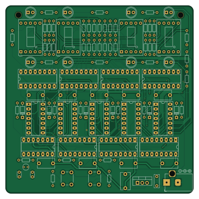
About the Digital clock PCB
Digital clock is an open source PCB design by guilhermegch, published on GitHub. It is a 2-layer board measuring 100 × 100 mm, with 96 components from 20 distinct parts.
Other key parts include the L7805, 4093, 4020, 4017 and 74HC251. By type, the board carries 47 resistors, 18 ICs, 14 diodes, 13 capacitors, 2 switches and 1 crystal.
It belongs with the displays & leds designs in this gallery.
From the project
This is a digital clock project
This is a crystal based clock is made using only common ICs: - Binary Counter (CD4020, CD4017, 74HC393) - AND gates (74HC08) - NAND gates (CD4093) - Multiplexer (74HC251) - 7 segments display decoder (CD4511)
This clock source is on a 32.768 kHz crystal. The signal is amplified by the NAND gates and sent to a frequency divider. Since 32786 = 2^15, we use the CD4020 14 stages with the output cascaded to a CD4017, so we have a stable 1 Hz oscillator.
Main components on the Digital clock
Digital clock bill of materials (BOM)
96 components, 20 distinct parts.
| Qty | Part | Footprint | Refs |
|---|---|---|---|
| 1 | L7805 | TO-220-3_Vertical | U1 |
| 1 | 4093 | DIP-14_W7.62mm_Socket_LongPads | U2 |
| 1 | 4020 | DIP-16_W7.62mm_Socket_LongPads | U3 |
| 1 | 4017 | DIP-16_W7.62mm_Socket_LongPads | U4 |
| 1 | 74HC251 | DIP-16_W7.62mm_Socket_LongPads | U5 |
| 3 | 74HC393 | DIP-14_W7.62mm_Socket_LongPads | U6, U9, U10 |
| 2 | 74HC08 | DIP-14_W7.62mm_Socket_LongPads | U7, U8 |
| 4 | 4511 | DIP-16_W7.62mm_Socket_LongPads | U11, U13, U15, U17 |
| 4 | 5611AH | D1X8K | U12, U14, U16, U18 |
| 1 | 32.768 Hz | Crystal_Round_D3.0mm_Vertical | Y1 |
| 1 | Jack-DC | BarrelJack_Horizontal | J1 |
| 2 | Tactile_switch | SW_PUSH_6mm_H5mm | SW1, SW2 |
| 6 | 1N4148 | D_DO-35_SOD27_P7.62mm_Horizontal | D1, D2, D3, D4, D5, D6 |
| 8 | LED_Small | LED_D5.0mm | D7, D8, D9, D10, D11, D12, D13, D14 |
| 1 | 330nF | C_Rect_L7.0mm_W2.5mm_P5.00mm | C1 |
| 10 | 100nF | C_Disc_D9.0mm_W5.0mm_P7.50mm | C2, C5, C6, C7, C8, C9, C10, C11 +2 |
| 2 | 22pF | C_Disc_D3.0mm_W2.0mm_P2.50mm | C3, C4 |
| 1 | 10M | R_Axial_DIN0204_L3.6mm_D1.6mm_P7.62mm_Horizontal | R1 |
| 10 | 10k | R_Axial_DIN0204_L3.6mm_D1.6mm_P7.62mm_Horizontal | R2, R3, R4, R5, R6, R7, R8, R9 +2 |
| 36 | 470 | R_Axial_DIN0204_L3.6mm_D1.6mm_P7.62mm_Horizontal | R12, R13, R14, R15, R16, R17, R18, R19 +28 |
Digital clock design files
The KiCad project lives in the guilhermegch/digital-clock repository on GitHub; these links point at the commit this page was built from.
Digital clock: common questions
How big is the Digital clock PCB?
The Digital clock measures 100 × 100 mm, has 2 copper layers and is 1.6 mm thick.
How many components are on the Digital clock?
96 components, from 20 distinct parts. The full bill of materials is listed on this page.
Where can I download the Digital clock design files?
From the guilhermegch/digital-clock repository on GitHub, which has the KiCad layout; the links under Design files point to each one.
Can I use the Digital clock design in my own project?
The repository has no license, so all rights stay with guilhermegch. Use it as a reference, and ask the author before reusing the design.
Similar boards
BM28B0.6-24DSBreakout
scottbez1
15.2 × 35.6 mm3 parts2LApache-2.022.2k
LevelShifterBreakout
15.2 × 20.3 mm5 parts2LApache-2.022.2k
View base
81.2 × 81.2 mm81 parts2LApache-2.022.2k
View screen
35 × 35 mm12 parts2LApache-2.022.2k
Display eval
byrantech
52.1 × 22.6 mm12 parts4LMIT4.3k
ChainlinkBase
98.4 × 190.5 mm119 parts2LApache-2.04.2k