
Akash-Chowa-DX

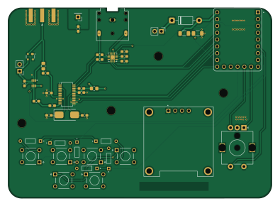
About the Akash-Chowa-DX PCB
Akash-Chowa-DX is an open source RP2040/RP2350 PCB design by Hasnat4763, published on GitHub under the MIT license. It is a 4-layer board measuring 98.5 × 70.9 mm, with 44 components from 29 distinct parts.
Its main chip is the RP2040-ZERO, from the RP2040/RP2350 family. Other key parts include the Si4735-D60-GU, TPA6132A2RTE and PE4259. By type, the board carries 13 capacitors, 6 switches, 4 ICs, 4 connectors, 4 inductors and 2 antennas.
It belongs with the power & battery, audio and displays & leds designs in this gallery.
From the project
Akash Chowa DX is a SW/MW/LW receiver designed based on the Si4735 Radio receiver IC paired with the RP2040 Zero Dev board.
Akash Chowa DX is a SW/MW/LW receiver designed based on the Si4735 Radio receiver IC paired with the RP2040 Zero Dev board.
I had an affection towards Radios from childhood. I sometimes try to receive SW stations on my 5$ budget radio I had gotten from a local store. But It does not work that efficiently and I needed a better receiver. Also the radio I currently have can not demodulate SSB (Single Sideband) and RDS transmitted by modern FM stations. So I designed it to fulfill my own requirements. It also helped me learn new things like impedance control.
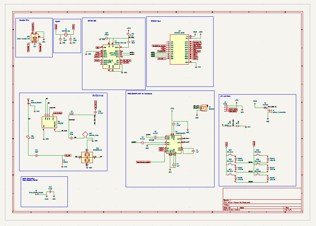
Main components on the Akash-Chowa-DX
Akash-Chowa-DX bill of materials (BOM)
44 components, 29 distinct parts — part numbers from the project's BOM.
| Qty | Part | Footprint | Refs |
|---|---|---|---|
| 1 | Si4735-D60-GU | SSOP-24_3.9x8.7mm_P0.635mm | U1 |
| 1 | RP2040-ZERO | MODULE_RP2040-ZERO | U2 |
| 1 | TPA6132A2RTE | WQFN-16-1EP_3x3mm_P0.5mm_EP1.6x1.6mm_ThermalVias | U4 |
| 1 | PE4259 | SOT65P215X110-6N | U5 |
| 1 | 32.768 kHz | Crystal_SMD_0603-2Pin_6.0x3.5mm_HandSoldering | Y1 |
| 1 | OLED | MODULE_DM-OLED096-636 | J2 |
| 1 | Speaker | Jack_3.5mm_CUI_SJ1-3523N_Horizontal | J3 |
| 1 | Battery Connection | PinHeader_1x02_P2.54mm_Vertical | J4 |
| 1 | Conn_01x01_Socket | PinHeader_1x01_P2.54mm_Vertical | J5 |
| 1 | Antenna_Shield | SMA_Amphenol_132289_EdgeMount | AE1 |
| 1 | Antenna_Loop | PinHeader_1x02_P2.54mm_Vertical | AE2 |
| 6 | 1N4148 | DIOAD753W49L380D172B | Diode1, Diode2, Diode3, Diode4, Diode5, Diode6 |
| 6 | SW_Push | SW_FSM8JH | SW2, SW3, SW4, SW5, SW6, SW7 |
| 1 | 1N5819 | D_DO-41_SOD81_P10.16mm_Horizontal | D1 |
| 1 | PRTR5V0U2X | SOT-143 | D10 |
| 1 | 2.5K | R_0805_2012Metric_Pad1.20x1.40mm_HandSolder | FB1 |
| 1 | 1k | R_0805_2012Metric_Pad1.20x1.40mm_HandSolder | FB2 |
| 1 | 180nH | L_0603_1608Metric_Pad1.05x0.95mm_HandSolder | L2 |
| 1 | 4.7uH | L_0603_1608Metric_Pad1.05x0.95mm_HandSolder | L3 |
| 1 | 2.2uF | C_0603_1608Metric_Pad1.08x0.95mm_HandSolder | C1 |
Show 9 more
| Qty | Part | Footprint | Refs |
|---|---|---|---|
| 2 | 1uF | C_0603_1608Metric_Pad1.08x0.95mm_HandSolder | C2, C7 |
| 2 | 22pF | C_0603_1608Metric_Pad1.08x0.95mm_HandSolder | C3, C4 |
| 3 | 0.47uF | C_0603_1608Metric_Pad1.08x0.95mm_HandSolder | C5, C6, C10 |
| 1 | 33pF | C_0603_1608Metric_Pad1.08x0.95mm_HandSolder | C11 |
| 1 | 0.1uF | C_0603_1608Metric_Pad1.08x0.95mm_HandSolder | C12 |
| 1 | 18pF | C_0603_1608Metric_Pad1.08x0.95mm_HandSolder | C14 |
| 1 | 22nF | C_0603_1608Metric_Pad1.08x0.95mm_HandSolder | C19 |
| 1 | 100nF | C_0603_1608Metric_Pad1.08x0.95mm_HandSolder | C20 |
| 2 | 100k | R_1206_3216Metric_Pad1.30x1.75mm_HandSolder | R3, R5 |
Akash-Chowa-DX design files
The KiCad project lives in the Hasnat4763/Akash-Chowa-DX repository on GitHub; these links point at the commit this page was built from.
- LayoutPCB/Akash Chowa DX.kicad_pcb
- SchematicPCB/Akash Chowa DX.kicad_sch
- BOMBOM.csv
Akash-Chowa-DX: common questions
What microcontroller does the Akash-Chowa-DX use?
The Akash-Chowa-DX is built around the RP2040-ZERO, from the RP2040/RP2350 family.
How big is the Akash-Chowa-DX PCB?
The Akash-Chowa-DX measures 98.5 × 70.9 mm, has 4 copper layers and is 1.6 mm thick.
How many components are on the Akash-Chowa-DX?
44 components, from 29 distinct parts, with part numbers taken from the project's own BOM. The full bill of materials is listed on this page.
Where can I download the Akash-Chowa-DX design files?
From the Hasnat4763/Akash-Chowa-DX repository on GitHub, which has the KiCad layout, the schematic and the BOM; the links under Design files point to each one.
Can I use the Akash-Chowa-DX design in my own project?
Yes, under the terms of its MIT license, which Hasnat4763 chose for the repository.
Can I test firmware for the Akash-Chowa-DX without the hardware?
Yes. HardLabs builds a simulation of the board from its netlist and BOM, so you can run and debug RP2040/RP2350 firmware against it before you order a PCB.
Similar boards
 RP2040/RP2350
Open Book Abridged Edition
joeycastillo
85 × 115 mm29 parts2LCC-BY-SA-4.08.1k RP2040/RP2350
Corne
foostan
277.2 × 107.5 mm164 parts2LCC-BY-4.07.7k RP2040/RP2350
Corne
277.2 × 107.5 mm164 parts2LCC-BY-4.07.7k RP2040/RP2350
LogicAnalyzer
gusmanb
57 × 55.2 mm6 parts2LGPL-3.05.0k RP2040/RP2350
Jitx design
55.5 × 65 mm26 parts4LGPL-3.05.0k RP2040/RP2350
Pro V2
kata0510
290.1 × 130 mm270 parts2LMIT2.3k