
K band fmcw radar

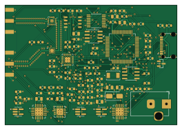
About the K band fmcw radar PCB
K band fmcw radar is an open source PCB design by HearnChristian, published on GitHub. It is a 4-layer board measuring 66 × 46 mm, with 99 components from 44 distinct parts.
Other key parts include the BGT24LTR11N16, ADF4159WCCPZ, OPA1656ID, TPS7A2033PDBVR and TPS7A2018PDBVR. By type, the board carries 55 capacitors, 22 resistors, 16 ICs, 4 connectors, 1 crystal and 1 diode.
It belongs with the audio and rf & radio designs in this gallery.
From the project
24 GHz FMCW radar front-end in KiCad (WIP): ADF4159 chirp synth, BGT24LTR11 transceiver, custom Marki AMM-8211PSM driver-amp symbol/footprint, OPA1656 IF, ADS8353 ADC, FT2232H USB.
A frequency-modulated continuous-wave (FMCW) radar front-end designed in KiCad — a single-board transceiver intended for ground-based ranging and weather / precipitation sensing. This repository holds the schematic capture, the project's custom KiCad libraries, and the generated netlist. Work in progress.
FMCW radar works by transmitting a continuous tone whose frequency is swept (chirped) linearly in time, then mixing the received echo against the transmitted signal. The frequency of the resulting beat tone is proportional to target range, so the whole signal chain is built around…
Main components on the K band fmcw radar
K band fmcw radar bill of materials (BOM)
99 components, 44 distinct parts.
| Qty | Part | Footprint | Refs |
|---|---|---|---|
| 1 | BGT24LTR11N16 | PQFN50P240X240X77-17N-V | U1 |
| 1 | ADF4159WCCPZ | CP_24_10 | U2 |
| 1 | OPA1656ID | D0008A_N | U3 |
| 2 | TPS7A2033PDBVR | DBV0005A-IPC_A | U4, U14 |
| 1 | TPS7A2018PDBVR | DBV0005A-IPC_A | U5 |
| 2 | TPS7A4700RGWT | RGW0020A-IPC_A | U6, U13 |
| 1 | FT2232HL-REEL | QFP50P1200X1200X160-64N | U7 |
| 1 | ADS8353IPW | PW16_TEX | U8 |
| 1 | ADP5600ACPZ-R7 | CP-16-17_ADI | U9 |
| 1 | 93LC56B-I/SN | SOIC8-N_MC_MCH | U10 |
| 1 | 445I23D12M00000 | 445I23D12M00000_CTS | U11 |
| 1 | AMM-8211PSM-22 AMM-8211PSM | QFN-16-1EP_3x3mm_P0.5mm_EP1.1x1.1mm_Marki | U12 |
| 1 | TPD2E009DBZR | SOT-23 | U15 |
| 1 | REF5025AID | SOIC-8_3.9x4.9mm_P1.27mm | U16 |
| 1 | ECS-TXO-2520MV-500-AN-TR | OSC_ECS-TXO-2520MV-500-AN-TR | Y1 |
| 1 | USB4215-03-A | CONN_8p94X6p5X3p16_12L_GCC | J1 |
| 1 | Barrel_Jack | BarrelJack_Horizontal | J2 |
| 2 | SMA-2.92mm-EndLaunch | SMA_Amphenol_132289_EdgeMount | J3, J4 |
| 1 | SS34 | D_SMA | D1 |
| 23 | 100nF | C_0603_1608Metric | C1, C2, C3, C4, C5, C6, C7, C8 +15 |
Show 24 more
| Qty | Part | Footprint | Refs |
|---|---|---|---|
| 1 | 3.3uF | C_0805_2012Metric | C16 |
| 1 | 910pF | C_0603_1608Metric | C17 |
| 1 | 15nF | C_0603_1608Metric | C18 |
| 1 | 270pF | C_0603_1608Metric | C19 |
| 3 | 100pF | C_0603_1608Metric | C20, C21, C51 |
| 10 | 1uF | C_0603_1608Metric | C24, C26, C34, C38, C39, C41, C45, C52 +2 |
| 7 | 10uF | C_0805_2012Metric | C25, C27, C40, C43, C44, C46, C47 |
| 2 | 18pF | C_0603_1608Metric | C28, C29 |
| 4 | 10nF | C_0603_1608Metric | C33, C48, C49, C50 |
| 2 | 560pF | C_0603_1608Metric | C36, C37 |
| 1 | 12k | R_0603_1608Metric | R1 |
| 1 | 4.7k | R_0603_1608Metric | R2 |
| 1 | 270R | R_0603_1608Metric | R3 |
| 1 | 560R | R_0603_1608Metric | R4 |
| 3 | 5.1k | R_0603_1608Metric | R5, R7, R8 |
| 1 | 16k | R_0603_1608Metric | R6 |
| 3 | 100k | R_0603_1608Metric | R11, R14, R19 |
| 2 | 1k | R_0603_1608Metric | R12, R15 |
| 2 | 18k | R_0603_1608Metric | R13, R16 |
| 1 | 0R | R_0603_1608Metric | R17 |
| 1 | 33k | R_0603_1608Metric | R18 |
| 2 | 10k | R_0603_1608Metric | R20, R22 |
| 1 | 2.2k | R_0603_1608Metric | R21 |
| 2 | 49.9R | R_0603_1608Metric | R23, R24 |
K band fmcw radar design files
The KiCad project lives in the HearnChristian/k-band-fmcw-radar repository on GitHub; these links point at the commit this page was built from.
- LayoutRadar1.kicad_pcb
- SchematicRadar1.kicad_sch
K band fmcw radar: common questions
How big is the K band fmcw radar PCB?
The K band fmcw radar measures 66 × 46 mm, has 4 copper layers and is 1.545 mm thick.
How many components are on the K band fmcw radar?
99 components, from 44 distinct parts. The full bill of materials is listed on this page.
Where can I download the K band fmcw radar design files?
From the HearnChristian/k-band-fmcw-radar repository on GitHub, which has the KiCad layout and the schematic; the links under Design files point to each one.
Can I use the K band fmcw radar design in my own project?
The repository has no license, so all rights stay with HearnChristian. Use it as a reference, and ask the author before reusing the design.
Similar boards
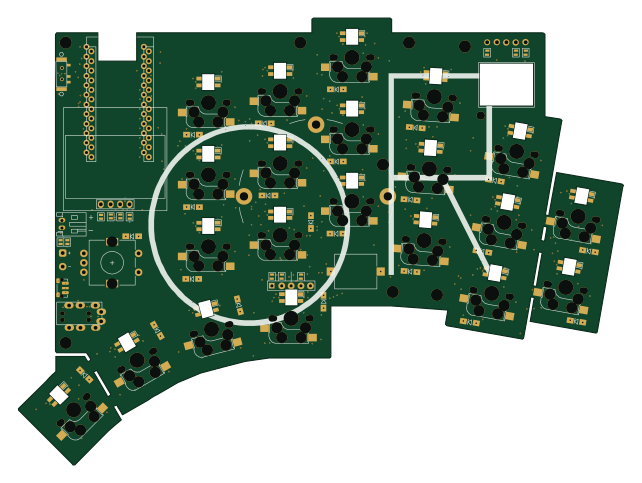
KLOR
GEIGEIGEIST
160.2 × 118.3 mm79 parts2LGPL-3.01.2k
USB
shanteacontrols
52 × 12.6 mm6 parts2LApache-2.0956
ButtonsLEDs
390 × 37 mm82 parts2LApache-2.0956
Pots
390 × 93 mm75 parts2LApache-2.0956
PicoGUS Hand386
polpo
29.2 × 75.2 mm43 parts4LGPL-2.0800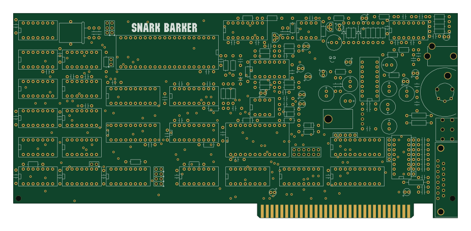
Snark barker
schlae
231.1 × 106.7 mm193 parts2LNo license687