
Deloop lite mk0

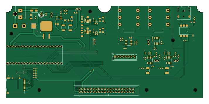
About the Deloop lite mk0 PCB
Deloop lite mk0 is an open source PCB design by hmcty, published on GitHub under the MIT license. It is a 4-layer board measuring 178 × 83.3 mm, with 84 components from 43 distinct parts.
Other key parts include the OPA2134, TL072, uA7805, H11L1 and LT1931. By type, the board carries 31 resistors, 25 capacitors, 10 ICs, 7 connectors, 5 jumpers and 4 diodes.
It belongs with the audio and displays & leds designs in this gallery.
From the project
Collection of personal KiCAD projects
System board for a simple, 2-track loop pedal.
Components: - Daisy Seed - Module carrying STM32H7 microcontroller, PCM3060 audio codec, and external SDRAM IC - Barrel jack port assuming center-negative 9V DC power input - +/-7V Power Supply - Imported design from a previous project, see Pedal Split Supply - 2x 1/4" mono jacks (1 line-in, 1 line-out) - 1x 3.5mm TRS MIDI input - 2x audio input buffer (OPA2134) - 2x audio output buffer (TL072) - 1x output mix stage (TL072) - 40-pin IDC header for UI and digital control connections - 8x JST XH socket for auxiliary audio connections - MicroSD…
Main components on the Deloop lite mk0
Deloop lite mk0 bill of materials (BOM)
84 components, 43 distinct parts.
| Qty | Part | Footprint | Refs |
|---|---|---|---|
| 1 | ~ | Electrosmith_Daisy_Seed | U1 |
| 1 | OPA2134 | SOIC-8_3.9x4.9mm_P1.27mm | U2 |
| 3 | TL072 | SOIC-8_3.9x4.9mm_P1.27mm | U3, U4, U5 |
| 1 | uA7805 | TO-263-2 | U6 |
| 1 | H11L1 | SMDIP-6_W9.53mm | U7 |
| 1 | LT1931 | TSOT-23-5_HandSoldering | U8 |
| 1 | TPS7A49 | MSOP-8-1EP_3x3mm_P0.65mm_EP1.68x1.88mm_ThermalVias | U9 |
| 1 | TPS7A30 | MSOP-8-1EP_3x3mm_P0.65mm_EP1.68x1.88mm_ThermalVias | U10 |
| 1 | Conn_01x02_Pin | PinHeader_1x02_P2.54mm_Vertical | J1 |
| 1 | Micro_SD_Card_Det2 | microSD_HC_Hirose_DM3AT-SF-PEJM5 | J3 |
| 2 | AudioJack3_Switch | Jack_6.35mm_Neutrik_NMJ6HCD2_Horizontal | J4, J5 |
| 1 | Barrel_Jack_Switch | BarrelJack_Horizontal | J6 |
| 1 | Conn_02x20_Odd_Even | IDC-Header_2x20_P2.54mm_Vertical | J9 |
| 1 | Conn_01x08_Socket | JST_XH_B8B-XH-AM_1x08_P2.50mm_Vertical | J10 |
| 2 | Jumper_2_Bridged | PinHeader_1x02_P2.54mm_Vertical | JP1, JP2 |
| 3 | Jumper_2_Open | PinHeader_1x02_P2.54mm_Vertical | JP3, JP4, JP5 |
| 1 | US1B | D_SMA | D5 |
| 1 | LED | LED_1206_3216Metric_Pad1.42x1.75mm_HandSolder | D6 |
| 1 | 1N4148 | Nexperia_CFP3_SOD-123W | D7 |
| 1 | D_Schottky | C_1206_3216Metric_Pad1.33x1.80mm_HandSolder | D8 |
Show 23 more
| Qty | Part | Footprint | Refs |
|---|---|---|---|
| 2 | 15u | L_1812_4532Metric_Pad1.30x3.40mm_HandSolder | L1, L2 |
| 10 | 100N | C_0603_1608Metric_Pad1.08x0.95mm_HandSolder | C1, C4, C7, C8, C9, C10, C12, C15 +2 |
| 2 | 150N C0G | C_1812_4532Metric_Pad1.57x3.40mm_HandSolder | C5, C6 |
| 1 | 10u | CP_Radial_D5.0mm_P2.00mm | C11 |
| 1 | 4.7u | C_0805_2012Metric_Pad1.18x1.45mm_HandSolder | C16 |
| 1 | 1u | C_1206_3216Metric_Pad1.33x1.80mm_HandSolder | C17 |
| 1 | 220p | C_0805_2012Metric_Pad1.18x1.45mm_HandSolder | C18 |
| 1 | 22u | C_0805_2012Metric_Pad1.18x1.45mm_HandSolder | C19 |
| 2 | 10u | C_1206_3216Metric_Pad1.33x1.80mm_HandSolder | C20, C21 |
| 4 | 10N | C_0805_2012Metric_Pad1.18x1.45mm_HandSolder | C22, C23, C24, C25 |
| 2 | 2.2u | C_0805_2012Metric_Pad1.18x1.45mm_HandSolder | C26, C27 |
| 5 | 47 K | R_0603_1608Metric_Pad0.98x0.95mm_HandSolder | R1, R2, R3, R4, R5 |
| 2 | 1M | R_0603_1608Metric_Pad0.98x0.95mm_HandSolder | R6, R7 |
| 2 | 47R 0.1% | R_0603_1608Metric_Pad0.98x0.95mm_HandSolder | R12, R13 |
| 4 | 100 0.1% | R_0603_1608Metric_Pad0.98x0.95mm_HandSolder | R14, R15, R16, R18 |
| 2 | 15K 0.1% | R_0603_1608Metric_Pad0.98x0.95mm_HandSolder | R17, R19 |
| 8 | 10K 0.1% | R_0603_1608Metric_Pad0.98x0.95mm_HandSolder | R20, R21, R22, R23, R24, R25, R26, R31 |
| 1 | 1K4 | R_0603_1608Metric_Pad0.98x0.95mm_HandSolder | R27 |
| 1 | 220R | R_0603_1608Metric_Pad0.98x0.95mm_HandSolder | R28 |
| 1 | 270R | R_0603_1608Metric_Pad0.98x0.95mm_HandSolder | R29 |
| 1 | 60K 0.1% | R_0603_1608Metric_Pad0.98x0.95mm_HandSolder | R30 |
| 2 | 604K 0.1% | R_0603_1608Metric_Pad0.98x0.95mm_HandSolder | R32, R34 |
| 2 | 123K 0.1% | R_0603_1608Metric_Pad0.98x0.95mm_HandSolder | R33, R35 |
Deloop lite mk0 design files
The KiCad project lives in the hmcty/kicad-ws repository on GitHub; these links point at the commit this page was built from.
Deloop lite mk0: common questions
How big is the Deloop lite mk0 PCB?
The Deloop lite mk0 measures 178 × 83.3 mm, has 4 copper layers and is 1.6 mm thick.
How many components are on the Deloop lite mk0?
84 components, from 43 distinct parts. The full bill of materials is listed on this page.
Where can I download the Deloop lite mk0 design files?
From the hmcty/kicad-ws repository on GitHub, which has the KiCad layout and the schematic; the links under Design files point to each one.
Can I use the Deloop lite mk0 design in my own project?
Yes, under the terms of its MIT license, which hmcty chose for the repository.
More boards in kicad-ws
Similar boards
BM28B0.6-24DSBreakout
scottbez1
15.2 × 35.6 mm3 parts2LApache-2.022.2k
LevelShifterBreakout
15.2 × 20.3 mm5 parts2LApache-2.022.2k
View base
81.2 × 81.2 mm81 parts2LApache-2.022.2k
View screen
35 × 35 mm12 parts2LApache-2.022.2k
Display eval
byrantech
52.1 × 22.6 mm12 parts4LMIT4.3k
ChainlinkBase
98.4 × 190.5 mm119 parts2LApache-2.04.2k