
Testerboard

About the Testerboard PCB
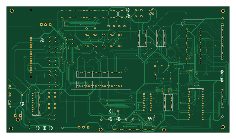
Testerboard is an open source PCB design by hprd, published on GitHub. It is a 2-layer board measuring 246.3 × 138.9 mm, with 81 components from 27 distinct parts.
Other key parts include the L7805, Z80CPU, 74LS14, 74LS02 and CY62256-70PC. By type, the board carries 25 resistors, 13 capacitors, 10 ICs, 10 diodes, 9 connectors and 1 crystal.
It belongs with the retro computing designs in this gallery.
From the project
UT Austin Fall 2025-Spring 2026 Senior Design Project for developing a Zilog Z80 CPU drop-in replacement using an FPGA.
Relevant links and information from previous group's iteration: - Instruction Set - Z80 User Manual - Master Reference Website - Timing Quirks
Main components on the Testerboard
Testerboard bill of materials (BOM)
81 components, 27 distinct parts.
| Qty | Part | Footprint | Refs |
|---|---|---|---|
| 1 | L7805 | TO254P1054X470X2600-3 | U1 |
| 1 | Z80CPU | 3M_Textool_240-1288-00-0602J_2x20_P2.54mm | U2 |
| 1 | 74LS14 | DIP-14_W7.62mm_Socket | U3 |
| 1 | 74LS02 | DIP-14_W7.62mm_Socket | U4 |
| 1 | CY62256-70PC | DIP-28_W15.24mm_Socket | U5 |
| 1 | LCD-16X2 | MODULE_LCD-16X2 | U6 |
| 1 | SST39SF010 | DIP_Socket-32_W11.9_W12.7_W15.24_W17.78_W18.5_3M_232-1285-00-0602J | U7 |
| 1 | 74HC138 | DIP-16_W7.62mm_Socket | U8 |
| 1 | 74HC244 | DIP-20_W7.62mm_Socket | U10 |
| 1 | 74LS32 | DIP-14_W7.62mm_Socket | U11 |
| 1 | ACH-4.000MHZ-EK | XTAL_ACH-4.000MHZ-EK | Y1 |
| 2 | Conn_01x03_Pin | PinHeader_1x03_P2.54mm_Vertical | J1, J3 |
| 1 | PJ-102A | BarrelJack_Horizontal | J2 |
| 4 | Conn_01x02_Pin | PinHeader_1x02_P2.54mm_Vertical | J4, J5, J6, J7 |
| 1 | Conn_01x16_Pin | PinHeader_1x16_P2.54mm_Vertical | J8 |
| 1 | Conn_01x08_Pin | PinHeader_1x08_P2.54mm_Vertical | J9 |
| 1 | NHD-12864WG-BTMI-V#N | NHD12864WGBTMIVN | DS1 |
| 2 | R_Potentiometer | Potentiometer_Alps_RK163_Single_Horizontal | RV1, RV2 |
| 1 | SW_Push | SW_PUSH_6mm | SW1 |
| 8 | SW_Push | SW_PUSH_6mm | SWB0, SWB1, SWB2, SWB3, SWB4, SWB5, SWB6, SWB7 |
Show 7 more
| Qty | Part | Footprint | Refs |
|---|---|---|---|
| 1 | TestPoint | Pin_D1.0mm_L10.0mm | TP/M1 |
| 10 | LED | LED_D5.0mm | D25, D26, D27, D28, D29, D30, D31, D32 +2 |
| 1 | 330nF | CP_Radial_D4.0mm_P2.00mm | C1 |
| 11 | 100nF | CP_Radial_D4.0mm_P2.00mm | C2, C3, C4, C6, C7, C8, C9, C10 +3 |
| 1 | 10uF | CP_Radial_D4.0mm_P2.00mm | C5 |
| 21 | 1K | R_Axial_DIN0204_L3.6mm_D1.6mm_P7.62mm_Horizontal | R1, R3, R8, R9, R10, R11, R12, R13 +13 |
| 4 | 10K | R_Axial_DIN0204_L3.6mm_D1.6mm_P7.62mm_Horizontal | R4, R5, R6, R7 |
Testerboard design files
The KiCad project lives in the hprd/z80-fpga-drop-in-replacement repository on GitHub; these links point at the commit this page was built from.
Testerboard: common questions
How big is the Testerboard PCB?
The Testerboard measures 246.3 × 138.9 mm, has 2 copper layers and is 1.6 mm thick.
How many components are on the Testerboard?
81 components, from 27 distinct parts. The full bill of materials is listed on this page.
Where can I download the Testerboard design files?
From the hprd/z80-fpga-drop-in-replacement repository on GitHub, which has the KiCad layout and the schematic; the links under Design files point to each one.
Can I use the Testerboard design in my own project?
The repository has no license, so all rights stay with hprd. Use it as a reference, and ask the author before reusing the design.
More boards in z80-fpga-drop-in-replacement
Similar boards
Amiga External
hoglet67
21.9 × 76.7 mm6 parts2LGPL-3.01.0k
Atari pickup
26.4 × 53.9 mm7 parts2LGPL-3.01.0k
Deniseadapter
26.7 × 62.2 mm16 parts2LGPL-3.01.0k
Analog
53.9 × 23.2 mm33 parts2LGPL-3.01.0k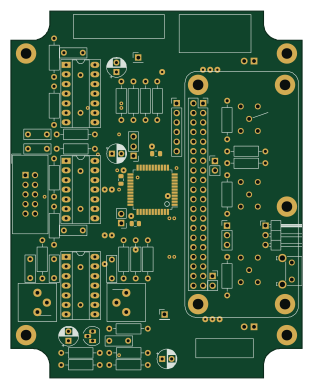
Rgb to hdmi
77 × 97 mm67 parts2LGPL-3.01.0k
Buffer
53.9 × 23.2 mm13 parts2LGPL-3.01.0k