
In13-Spectrum-Analyser

About the In13-Spectrum-Analyser PCB
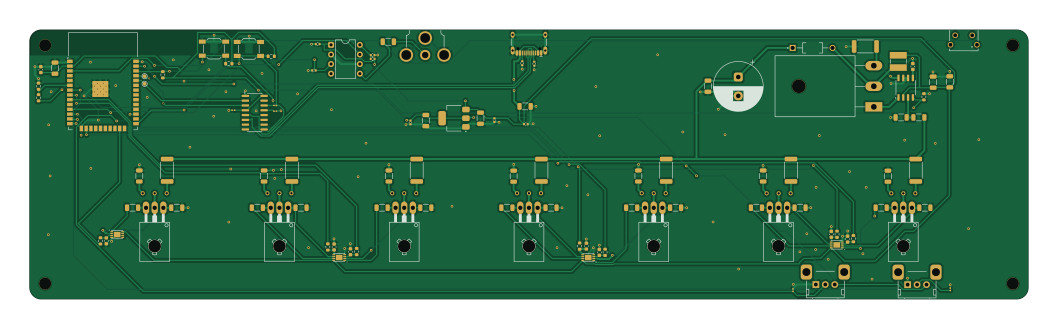
In13-Spectrum-Analyser is an open source ESP32 PCB design by ImNoahDev, published on GitHub under the CC-BY-NC-4.0 license. It is a 2-layer board measuring 264.2 × 71.1 mm, with 109 components from 42 distinct parts.
Its main chip is the ESP32-WROOM-32, from the ESP32 family. Other key parts include the AMS1117-3.3, MSGEQ7, MCP6002-XMC, CH340C and MAX1771XSA. By type, the board carries 47 resistors, 29 capacitors, 9 ICs, 8 transistors, 3 switches and 2 connectors.
It belongs with the iot & wireless, test & measurement and displays & leds designs in this gallery.
From the project
I have designed an audio spectrum analyser that breaks an audio signal down into 7 frequency bands and displays each band on an in13 nixie tube. My project has Wifi allowing for smart home control. My project has a volume (changes sensitivity) and a brightness potentiometer. Each
I have designed an audio spectrum analyser that breaks an audio signal down into 7 frequency bands and displays each band on an in13 nixie tube. My project has Wifi allowing for smart home control. My project has a volume (changes sensitivity) and a brightness potentiometer. Each PCB takes a single audio signal input and 2 can be used for full stereo.
The case uses a laser cut kerf bend to allow the wrap around sheet to be cut in a single part.

Main components on the In13-Spectrum-Analyser
In13-Spectrum-Analyser bill of materials (BOM)
109 components, 42 distinct parts — part numbers from the project's BOM.
| Qty | Part | Footprint | Refs |
|---|---|---|---|
| 1 | AMS1117-3.3 | SOT-223-3_TabPin2 | U1 |
| 1 | MSGEQ7 | DIP-8_W7.62mm | U2 |
| 1 | ESP32-WROOM-32 | ESP32-WROOM-32 | U3 |
| 4 | MCP6002-XMC MCP6002-xMC | DFN-8-1EP_3x2mm_P0.5mm_EP1.75x1.45mm | U4, U5, U6, U18 |
| 1 | CH340C | SOIC-16_3.9x9.9mm_P1.27mm | U7 |
| 1 | MAX1771XSA MAX1771xSA | SO-8_3.9x4.9mm_P1.27mm | U11 |
| 7 | MJE340_ | TO126 | Q1, Q2, Q3, Q4, Q5, Q6, Q7 |
| 1 | IRFP250N Infineon Technologies | TO-247-3_Horizontal_TabDown | Q8 |
| 1 | USB_C_RECEPTACLE_USB2.0_14P USB_C_Receptacle_USB2.0_14P | USB_C_Receptacle_HCTL_HC-TYPE-C-16P-01A | J1 |
| 1 | Conn_Coaxial | RCA-Phono_CUI-Devices_RCJ-01X_Horizontal | J3 |
| 7 | ~ | nixies-us-IN-13 | N1, N2, N3, N4, N5, N6, N7 |
| 2 | 10K 10k | Potentiometer_Alps_RK09K_Single_Horizontal | RV2, RV3 |
| 2 | SW_Push | SW_SPST_SKQG_WithStem | SW1, SW3 |
| 1 | SW_Push | 4312560387X6 | SW2 |
| 1 | UF4004 | DIOAD1055W87L533D272 | D2 |
| 1 | 56 uH | L_Ferrocore_DLG-0403 | L1 |
| 1 | 4.7uF 10v | C_1206_3216Metric | C1 |
| 3 | 0.1uF 10v | C_0402_1005Metric | C2, C9, C10 |
| 1 | 10V 3.3uF | C_1206_3216Metric | C3 |
| 2 | 10V 0.1uF | C_0402_1005Metric | C4, C6 |
Show 22 more
| Qty | Part | Footprint | Refs |
|---|---|---|---|
| 1 | 10v 22uF | C_1206_3216Metric | C5 |
| 1 | 10V 1uF | C_1206_3216Metric | C7 |
| 1 | 33PF 33pF | C_0402_1005Metric | C8 |
| 2 | 10UF 10uF | C_1206_3216Metric | C11, C22 |
| 9 | 0.1UF 0.1uF | C_0603_1608Metric | C12, C13, C14, C15, C16, C17, C18, C19 +1 |
| 1 | 100uF 16v | C_1206_3216Metric | C21 |
| 1 | 47uF 200V | CP_Radial_D13.0mm_P5.00mm | C23 |
| 1 | 0.1uF 250v | C_1206_3216Metric | C24 |
| 5 | 0.1UF 0.1uF | C_0201_0603Metric | C25, C26, C27, C28, C29 |
| 2 | 5.1K | R_0402_1005Metric | R1, R2 |
| 1 | 200K | R_0402_1005Metric | R3 |
| 4 | 10K 10k | R_0603_1608Metric | R4, R7, R46, R47 |
| 1 | 18K | R_0603_1608Metric | R5 |
| 1 | 33K 33k | R_0603_1608Metric | R6 |
| 7 | 4.7K 4.7k | R_0603_1608Metric | R8, R13, R18, R23, R28, R33, R38 |
| 7 | 470k 1/4w | R_1206_3216Metric | R9, R15, R20, R25, R30, R35, R40 |
| 7 | 15k 1W | R_2512_6332Metric | R10, R14, R19, R24, R29, R34, R39 |
| 7 | 2.2k 1/4W | R_1206_3216Metric | R11, R16, R21, R26, R31, R36, R41 |
| 7 | 820 1/4w | R_1206_3216Metric | R12, R17, R22, R27, R32, R37, R42 |
| 1 | 0.05 1w | R_2512_6332Metric | R43 |
| 1 | 820k 0.25w 200v | R_1206_3216Metric | R44 |
| 1 | 10k 0.25w 200v | R_1206_3216Metric | R45 |
In13-Spectrum-Analyser design files
The KiCad project lives in the ImNoahDev/In13-Spectrum-Analyser repository on GitHub; these links point at the commit this page was built from.
In13-Spectrum-Analyser: common questions
What microcontroller does the In13-Spectrum-Analyser use?
The In13-Spectrum-Analyser is built around the ESP32-WROOM-32, from the ESP32 family.
How big is the In13-Spectrum-Analyser PCB?
The In13-Spectrum-Analyser measures 264.2 × 71.1 mm, has 2 copper layers and is 1.6 mm thick.
How many components are on the In13-Spectrum-Analyser?
109 components, from 42 distinct parts, with part numbers taken from the project's own BOM. The full bill of materials is listed on this page.
Where can I download the In13-Spectrum-Analyser design files?
From the ImNoahDev/In13-Spectrum-Analyser repository on GitHub, which has the KiCad layout, the schematic and the BOM; the links under Design files point to each one.
Can I use the In13-Spectrum-Analyser design in my own project?
It is published under CC-BY-NC-4.0, which limits how it may be reused; read the license before building on it.
Can I test firmware for the In13-Spectrum-Analyser without the hardware?
Yes. HardLabs builds a simulation of the board from its netlist and BOM, so you can run and debug ESP32 firmware against it before you order a PCB.
Similar boards
 ESP32
ESP32Open Book Abridged Edition
joeycastillo
85 × 115 mm65 parts2LCC-BY-SA-4.08.1k ESP32
ESP32Esp32 minimal
atopile
36.2 × 26.8 mm20 parts2LMIT4.0k ESP32
ESP32Badge
56.3 × 39 mm239 parts4LMIT4.0k ESP32
ESP32Controller
StuckAtPrototype
29 × 74 mm58 parts4LApache-2.03.8k ESP32
ESP32Racer
36 × 50.2 mm70 parts4LApache-2.03.8k ESP32
ESP32Bitaxe
skot
56.5 × 99.8 mm86 parts4LCERN-OHL-S-2.01.4k