
Project-Mach-1

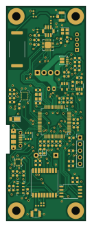
About the Project-Mach-1 PCB
Project-Mach-1 is an open source Microchip SAM PCB design by ImperialSpaceSociety, published on GitHub. It is a 4-layer board measuring 30.5 × 82.6 mm, with 82 components from 49 distinct parts.
Its main chip is the ATSAMD21J18A-AU, from the Microchip SAM family. Other key parts include the IIS2MDC, 0433BM41A0019E, SI4463, MAX-M8C and SI7232DN. By type, the board carries 36 capacitors, 16 resistors, 12 ICs, 7 connectors, 4 inductors and 3 diodes.
It belongs with the rf & radio and sensors designs in this gallery.
From the project
This is the code and hardware designs for the high powered rocketry project at the Imperial College Space Society
Flight Computer docs - Top Level Specfications and Documents
Each Module description has the following structure:
ICSS Specifications External specifications, references and documentation Electronic Hardware (schematics and PCB) Firmware * Physical Hardware (CAD)
The Flight Computer has these key role: Unambiguously capture flight data for subsequent analysis Verify and prove performance record data ( Mach) Support it's own successful recovery

Main components on the Project-Mach-1
Project-Mach-1 bill of materials (BOM)
82 components, 49 distinct parts — part numbers from the project's BOM.
| Qty | Part | Footprint | Refs |
|---|---|---|---|
| 1 | IIS2MDC LSM9DS1 | LGA-24L_3x3.5mm_P0.43mm | U1 |
| 1 | 0433BM41A0019E | BALUN_0433BM41A0019E | U2 |
| 1 | SI4463 Si4463 | QFN-20-1EP_4x4mm_P0.5mm_EP2.6x2.6mm_ThermalVias | U3 |
| 1 | MAX-M8C MAX-M8Q | ublox_MAX | U4 |
| 1 | SI7232DN H3LIS100DL | TFLGA-16_3x3mm | U5 |
| 1 | SI7232DN Si7232DN | Vishay_PowerPAK_1212-8_Dual | U6 |
| 1 | ATSAMD21J18A-AU | TQFP-64_10x10mm_P0.5mm | U7 |
| 1 | MS5607-02BA | LGA-8_3x5mm_P1.25mm | U8 |
| 1 | STF202-22T1G | TSOP-6_1.65x3.05mm_P0.95mm | U9 |
| 1 | ATSAML21J18B-AUT W25Q64JVSSIM | SOIC-8_5.23x5.23mm_P1.27mm | U11 |
| 1 | MAX40200AUK | SOT-23-5 | U14 |
| 1 | LD3985G33R_TSOT23 LD3985M33R_TSOT23 | TSOT-23-5 | U15 |
| 1 | TM-32.000-AF3-33-S-OSCILLATOR TM-32.000-AF3-33-S-Oscillator | Crystal_SMD_2520-4Pin_2.5x2.0mm | X1 |
| 1 | 16MHZ 16MHz | Crystal_SMD_2520-4Pin_2.5x2.0mm | Y3 |
| 1 | CONN_01X05 Conn_01x05 | PinHeader_1x05_P2.54mm_Vertical | J1 |
| 1 | USB_B_Micro | USB_Micro-B_Molex-105017-0001 | J2 |
| 1 | SCREW_TERMINAL_01X04 Screw_Terminal_01x04 | TerminalBlock_TE_282834-4_1x04_P2.54mm_Horizontal | J3 |
| 1 | CONN_01X02 Conn_01x02 | JST_PH_B2B-PH-K_1x02_P2.00mm_Vertical | J4 |
| 1 | SCREW_TERMINAL_01X04 Conn_01x04 | NS-Tech_Grove_1x04_P2mm_Vertical | J5 |
| 2 | Conn_Coaxial | U.FL_Hirose_U.FL-R-SMT-1_Vertical | J6, J7 |
Show 29 more
| Qty | Part | Footprint | Refs |
|---|---|---|---|
| 1 | YAGEO434 Yageo434 | Yageo434 | ANT1 |
| 1 | Buzzer | Buzzer_12x9.5RM7.6 | BZ1 |
| 1 | RED_LED | LED_0603_1608Metric | D1 |
| 1 | BLUE_LED | LED_0603_1608Metric | D2 |
| 1 | DFLS130L | D_PowerDI-123 | D3 |
| 1 | L_Core_Ferrite | L_0603_1608Metric | L1 |
| 1 | 27NH 27nH | R_0402_1005Metric | L2 |
| 1 | 0R | L_0402_1005Metric | L3 |
| 1 | 220NH 220nH | L_0603_1608Metric | L8 |
| 5 | 10UF 10uF | C_0603_1608Metric | C1, C2, C5, C12, C92 |
| 9 | 100NF 100nF | C_0603_1608Metric | C3, C4, C6, C7, C11, C23, C89, C91 +1 |
| 1 | 10NF 10nF | C_0402_1005Metric | C8 |
| 2 | 270PF 270pF | C_0402_1005Metric | C9, C19 |
| 1 | NF | C_0402_1005Metric | C10 |
| 2 | 10uF | C_0603_1608Metric | C13, C18 |
| 5 | 100nF | C_0603_1608Metric | C14, C15, C16, C17, C25 |
| 2 | 10NF 10nF | C_0603_1608Metric | C20, C34 |
| 1 | 33NF 33nF | C_0603_1608Metric | C21 |
| 4 | 1UF 1uF | C_0603_1608Metric | C22, C35, C36, C90 |
| 1 | 10nF | C_0603_1608Metric | C24 |
| 1 | 220NF 220nF | C_0603_1608Metric | C77 |
| 2 | 15PF 15pF | C_0603_1608Metric | C86, C88 |
| 4 | 1.6K | R_0603_1608Metric | R1, R12, R25, R26 |
| 1 | 10 Ohm | R_0402_1005Metric | R2 |
| 2 | 3.3K | R_0603_1608Metric | R3, R13 |
| 2 | 4.7K | R_0603_1608Metric | R4, R8 |
| 4 | 100K 120K | R_0603_1608Metric | R5, R15, R28, R29 |
| 2 | 27K | R_0603_1608Metric | R6, R16 |
| 1 | NF | R_0402_1005Metric | R7 |
Project-Mach-1 design files
The KiCad project lives in the ImperialSpaceSociety/Project-Mach-1 repository on GitHub; these links point at the commit this page was built from.
Project-Mach-1: common questions
What microcontroller does the Project-Mach-1 use?
The Project-Mach-1 is built around the ATSAMD21J18A-AU, from the Microchip SAM family.
How big is the Project-Mach-1 PCB?
The Project-Mach-1 measures 30.5 × 82.6 mm, has 4 copper layers and is 1.6 mm thick.
How many components are on the Project-Mach-1?
82 components, from 49 distinct parts, with part numbers taken from the project's own BOM. The full bill of materials is listed on this page.
Where can I download the Project-Mach-1 design files?
From the ImperialSpaceSociety/Project-Mach-1 repository on GitHub, which has the KiCad layout and the BOM; the links under Design files point to each one.
Can I use the Project-Mach-1 design in my own project?
The repository has no license, so all rights stay with ImperialSpaceSociety. Use it as a reference, and ask the author before reusing the design.
Can I test firmware for the Project-Mach-1 without the hardware?
Yes. HardLabs builds a simulation of the board from its netlist and BOM, so you can run and debug Microchip SAM firmware against it before you order a PCB.
Similar boards
 Microchip SAM
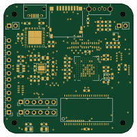
Fpgaboy
Wren6991
50 × 50 mm89 parts4LNo license508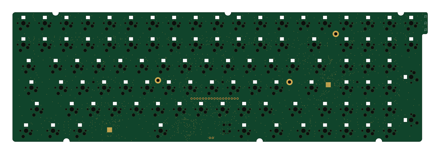 Microchip SAM
Kira
kiibohd
366.9 × 114.3 mm400 partsCERN-OHL-1.2415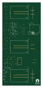 Microchip SAM
DSKY driver
benkrasnow
43 × 92.3 mm44 partsMIT258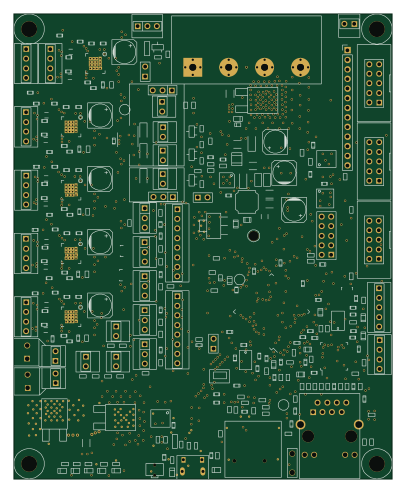 Microchip SAM
Duet 2 Maestro
Duet3D
100 × 123 mm336 partsCERN-OHL-1.2257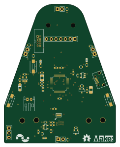 Microchip SAM
Makennbot
idlehandsdev
60 × 75 mm53 parts2LNo license175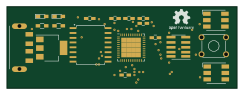 Microchip SAM
Oxidized flash
blakesmith
61 × 21.6 mm19 parts2LNo license167