
EverAliveSensor

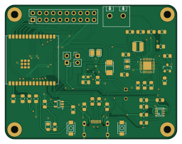
About the EverAliveSensor PCB
EverAliveSensor is an open source ESP32 PCB design by jfm92, published on GitHub under the CC-BY-NC-4.0 license. It is a 2-layer board measuring 64 × 50 mm, with 50 components from 34 distinct parts.
Its main chip is the ESP32-C6-WROOM-1-N8, from the ESP32 family. Other key parts include the AP2112K-3.3TRG1, AEM10941-QFN, TPS63900DSKR, BME680 and DB301V-5.0-2P-BU-S. By type, the board carries 18 resistors, 15 capacitors, 6 ICs, 3 connectors, 3 inductors and 2 switches.
It belongs with the sensors, iot & wireless and power & battery designs in this gallery.
From the project
Solar-powered BLE environmental sensor (temp, humidity, pressure) with a 50F supercapacitor — potentially infinite lifetime, 19-day dark autonomy. ESP32 + BME680. Experimental.
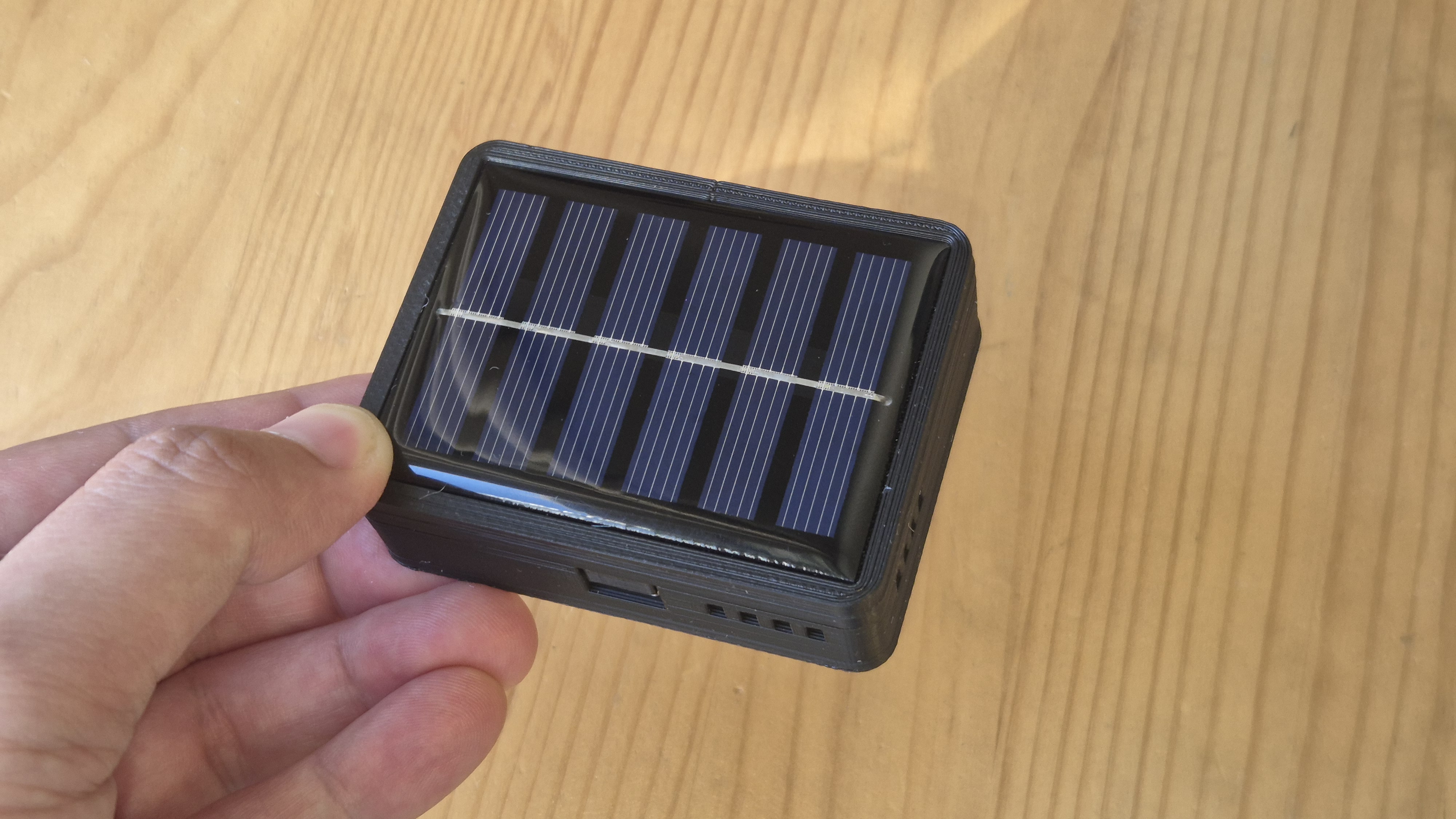
An ultra-low-power environmental sensor beacon that runs on solar energy — including indoor ambient light. With a 50 F supercapacitor as its energy reservoir, the device can operate for up to 19 days without any light source, and has the potential for indefinite lifetime under normal indoor illumination.
1. Wakes from deep sleep. 2. Reads temperature, humidity, and pressure from the BME680 sensor. 3. Broadcasts the data as a BLE advertisement for ~20 ms. 4. Goes back to deep sleep for 5 minutes.
Main components on the EverAliveSensor
EverAliveSensor bill of materials (BOM)
50 components, 34 distinct parts.
| Qty | Part | Footprint | Refs |
|---|---|---|---|
| 1 | ESP32-C6-WROOM-1-N8 ESPRESSIF(乐鑫) | WIRELM-SMD_ESP32-C6-WROOM-1 | U1 |
| 1 | AP2112K-3.3TRG1 DIODES(美台) | SOT-25-5_L2.9-W1.6-P0.95-LS2.8-BL | U2 |
| 1 | AEM10941-QFN | QFN50P500X500X90-29N | U3 |
| 1 | TPS63900DSKR | IC_TPS63900DSKR | U4 |
| 1 | BME680 Bosch(博世) | LGA-8_L3.0-W3.0-P0.80-TR | U5 |
| 1 | DB301V-5.0-2P-BU-S DB301V-5.0-2P DORABO(地博电气) | CONN-TH_2P-P5.00_L7.6-W10.0 | U6 |
| 1 | LBSS138LT1G LRC(乐山无线电) | SOT-23_L2.9-W1.3-P1.90-LS2.4-BR | Q2 |
| 2 | Conn_01x02_Pin | PinHeader_1x02_P2.54mm_Vertical | J1, J3 |
| 1 | Conn_02x10_Counter_Clockwise | PinHeader_2x10_P2.54mm_Vertical | J2 |
| 2 | HX 3x4x2-2P-1.6N TACTILE SWITCH HX 3X4X2-2P-1.6N TACTILE SWITCH hanxia(韩下) | KEY-SMD_L4.0-W3.0-LS4.9-1 | SW1, SW2 |
| 1 | TYPE-C-31-M-12 韩国韩荣 | USB-C_SMD-TYPE-C-31-M-12_1 | USBC1 |
| 1 | LED | LED_0805_2012Metric_Pad1.15x1.40mm_HandSolder | D1 |
| 1 | CB2012T100K TAIYO YUDEN(太诱) | L0805 | L1 |
| 1 | SRN3015-100M BOURNS | IND-SMD_L3.0-W3.0 | L2 |
| 1 | DFE252010F-2R2M=P2 muRata(村田) | L1008 | L3 |
| 3 | 1uF | C_0805_2012Metric_Pad1.18x1.45mm_HandSolder | C1, C2, C6 |
| 5 | 10uF | C_0805_2012Metric_Pad1.18x1.45mm_HandSolder | C3, C5, C7, C10, C12 |
| 1 | 22uF | C_0805_2012Metric_Pad1.18x1.45mm_HandSolder | C4 |
| 1 | AHCR-S04R0SA506Q | CAPPRD350W65D800H2700 | C9 |
| 1 | 0.1uF | C_0805_2012Metric_Pad1.18x1.45mm_HandSolder | C11 |
Show 14 more
| Qty | Part | Footprint | Refs |
|---|---|---|---|
| 2 | 100nF | C_0805_2012Metric_Pad1.18x1.45mm_HandSolder | C13, C14 |
| 1 | 100uF | C_0603_1608Metric_Pad1.08x0.95mm_HandSolder | C15 |
| 1 | CA45-B-16V-22uF-M CA45-B-16V-22UF-M CEC(振华新云) | CAP-SMD_L3.5-W2.8-R-RD | C16 |
| 2 | 5.1K | R_0805_2012Metric_Pad1.20x1.40mm_HandSolder | R1, R2 |
| 2 | 22 | R_0805_2012Metric_Pad1.20x1.40mm_HandSolder | R3, R4 |
| 4 | 1M | R_0805_2012Metric_Pad1.20x1.40mm_HandSolder | R5, R6, R7, R8 |
| 1 | 6.19M | R_0805_2012Metric_Pad1.20x1.40mm_HandSolder | R9 |
| 1 | 715K | R_0805_2012Metric_Pad1.20x1.40mm_HandSolder | R10 |
| 1 | 750K | R_0805_2012Metric_Pad1.20x1.40mm_HandSolder | R11 |
| 1 | 2.43M | R_0805_2012Metric_Pad1.20x1.40mm_HandSolder | R12 |
| 1 | 36.5K | R_0805_2012Metric_Pad1.20x1.40mm_HandSolder | R13 |
| 2 | 10K | R_0805_2012Metric_Pad1.20x1.40mm_HandSolder | R14, R15 |
| 2 | 4.7K | R_0805_2012Metric_Pad1.20x1.40mm_HandSolder | R16, R17 |
| 1 | 220 | R_0805_2012Metric_Pad1.20x1.40mm_HandSolder | R18 |
EverAliveSensor design files
The KiCad project lives in the jfm92/everAliveSensor repository on GitHub; these links point at the commit this page was built from.
EverAliveSensor: common questions
What microcontroller does the EverAliveSensor use?
The EverAliveSensor is built around the ESP32-C6-WROOM-1-N8, from the ESP32 family.
How big is the EverAliveSensor PCB?
The EverAliveSensor measures 64 × 50 mm, has 2 copper layers and is 1.6 mm thick.
How many components are on the EverAliveSensor?
50 components, from 34 distinct parts. The full bill of materials is listed on this page.
Where can I download the EverAliveSensor design files?
From the jfm92/everAliveSensor repository on GitHub, which has the KiCad layout and the schematic; the links under Design files point to each one.
Can I use the EverAliveSensor design in my own project?
It is published under CC-BY-NC-4.0, which limits how it may be reused; read the license before building on it.
Can I test firmware for the EverAliveSensor without the hardware?
Yes. HardLabs builds a simulation of the board from its netlist and BOM, so you can run and debug ESP32 firmware against it before you order a PCB.
Similar boards
 ESP32
Open Book Abridged Edition
joeycastillo
85 × 115 mm65 parts2LCC-BY-SA-4.08.1k ESP32
Powertrain
byrantech
64 × 45.4 mm171 parts4LMIT4.3k ESP32
Badge
atopile
56.3 × 39 mm239 parts4LMIT4.0k ESP32
Esp32 minimal
36.2 × 26.8 mm20 parts2LMIT4.0k ESP32
Controller
StuckAtPrototype
29 × 74 mm58 parts4LApache-2.03.8k ESP32
Racer
36 × 50.2 mm70 parts4LApache-2.03.8k