
MGP Decoder adapter board to RJ45 loop


About the MGP Decoder adapter board to RJ45 loop
MGP Decoder adapter board to RJ45 loop is an open source PCB design by jgraichen, published on GitHub under the CC-BY-SA-4.0 license. It is a 2-layer board measuring 70 × 30 mm, with 8 components from 6 distinct parts.
By type, the board carries 5 connectors and 3 jumpers.
It belongs with the displays & leds designs in this gallery.
From the project
Adapter PCB to connect Watti LED driver boards via RJ45 cables to MGP signal decoders. The adapter board supports connecting multiple RJ45 loops in a chain.
Adapter PCB to connect Watti LED driver boards via RJ45 cables to MGP signal decoders. The adapter board supports connecting multiple RJ45 loops in a chain.
The control signal from the signal decoder consists of three wires, a ground and power line, and a single data wire. The signals are passed on to the RJ45 cables:
LED on driver boards are controlled by the physical ordering on the data signal line. To order signals in a specific ordering, the RJ45 pinout supports returning the data signal from one RJ45 cable and pass it to the next. The last Watti LED driver must have the jumper JR1 set…
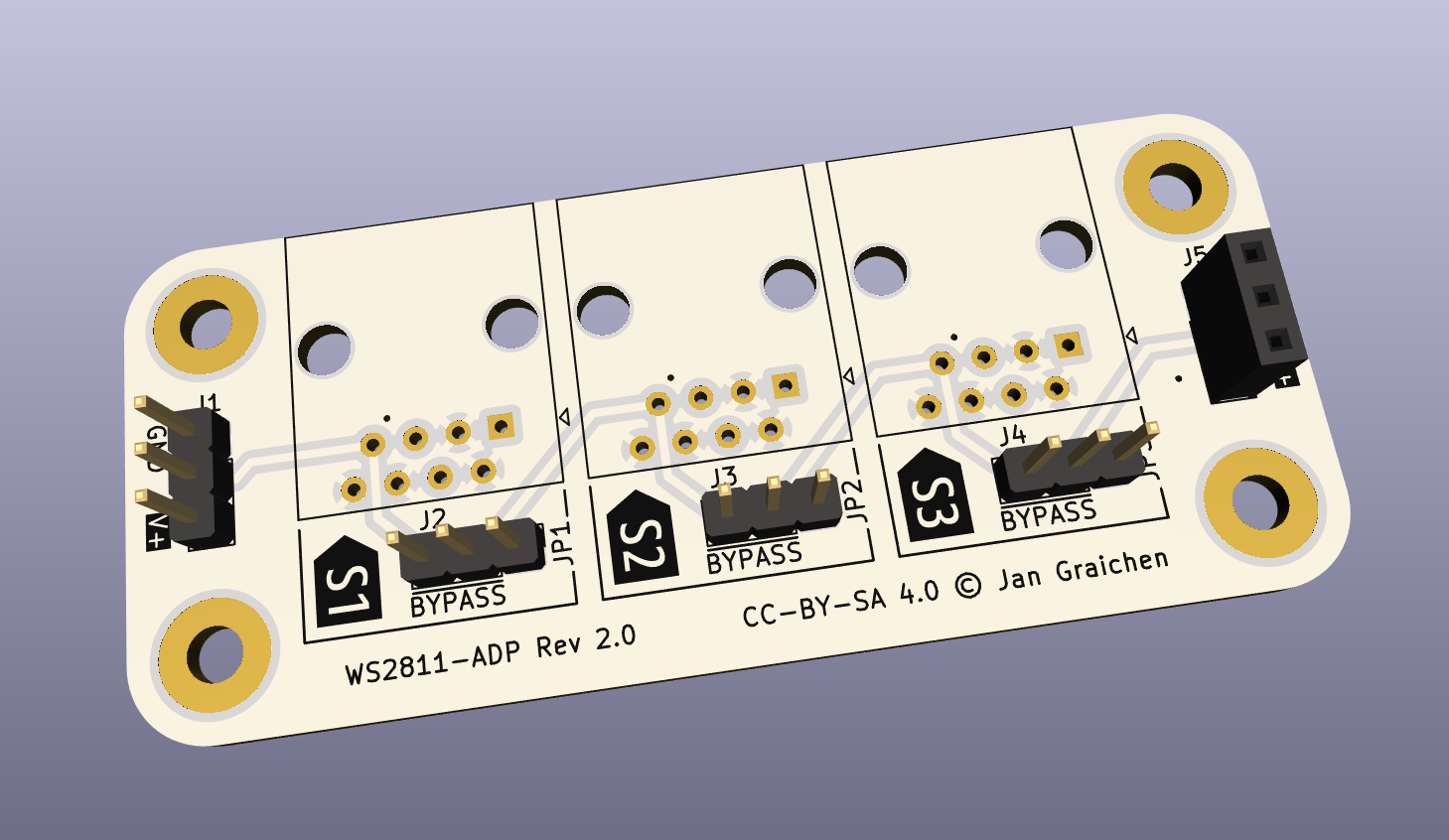
MGP Decoder adapter board to RJ45 loop bill of materials (BOM)
8 components, 6 distinct parts.
| Qty | Part | Footprint | Refs |
|---|---|---|---|
| 1 | Conn_01x03_Pin | PinHeader_1x03_P2.54mm_Vertical | J1 |
| 1 | RJ45 P1 | RJ45_Amphenol_54602-x08_Horizontal | J2 |
| 1 | RJ45 P2 | RJ45_Amphenol_54602-x08_Horizontal | J3 |
| 1 | RJ45 P3 | RJ45_Amphenol_54602-x08_Horizontal | J4 |
| 1 | Conn_01x03_Socket | PinSocket_1x03_P2.54mm_Vertical | J5 |
| 3 | Jumper_3_Bridged12 | PinHeader_1x03_P2.54mm_Vertical | JP1, JP2, JP3 |
MGP Decoder adapter board to RJ45 loop design files
The KiCad project lives in the jgraichen/railway-signals repository on GitHub; these links point at the commit this page was built from.
MGP Decoder adapter board to RJ45 loop: common questions
How big is the MGP Decoder adapter board to RJ45 loop?
The MGP Decoder adapter board to RJ45 loop measures 70 × 30 mm, has 2 copper layers and is 1.6 mm thick.
How many components are on the MGP Decoder adapter board to RJ45 loop?
8 components, from 6 distinct parts. The full bill of materials is listed on this page.
Where can I download the MGP Decoder adapter board to RJ45 loop design files?
From the jgraichen/railway-signals repository on GitHub, which has the KiCad layout and the schematic; the links under Design files point to each one.
Can I use the MGP Decoder adapter board to RJ45 loop design in my own project?
Yes, under the terms of its CC-BY-SA-4.0 license, which jgraichen chose for the repository.
More boards in railway-signals
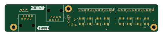
WS2811 LED Driver 24 (2 Signals)
140 × 25 mm16 parts2LCC-BY-SA-4.01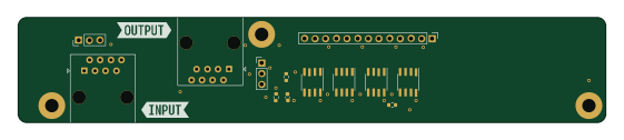
WS2811 LED Driver 12 (1 Signal)
140 × 25 mm12 parts2LCC-BY-SA-4.01
MS
6.6 × 13.6 mm9 parts2LCC-BY-SA-4.01
WS2811 LED Driver 9LS (2 Lichtsperrsignal)
60 × 45 mm8 parts2LCC-BY-SA-4.01
KS-Hauptsignal
6.6 × 13.6 mm8 parts2LCC-BY-SA-4.01
KS-Signalschirm für mehrfarbige Optik
6.6 × 13.6 mm7 parts2LCC-BY-SA-4.01
WS2811 LED Driver 6LS (1 Lichtsperrsignal)
60 × 45 mm7 parts2LCC-BY-SA-4.01
KS-Vorsignal
6.6 × 10.8 mm4 parts2LCC-BY-SA-4.01
Similar boards

LevelShifterBreakout
scottbez1
15.2 × 20.3 mm5 parts2LApache-2.022.2k
View base
81.2 × 81.2 mm81 parts2LApache-2.022.2k
View screen
35 × 35 mm12 parts2LApache-2.022.2k
BM28B0.6-24DSBreakout
15.2 × 35.6 mm3 parts2LApache-2.022.2k
ChainlinkDriverTester
198.1 × 95.3 mm123 parts2LApache-2.04.2k
ChainlinkBase
98.4 × 190.5 mm119 parts2LApache-2.04.2k