
Receiver

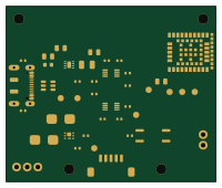
About the Receiver PCB
Receiver is an open source PCB design by JMET04, published on GitHub under the MIT license. It is a 4-layer board measuring 50 × 42 mm, with 22 components from 22 distinct parts.
Other key parts include the NINA-B302-00B-00, TPS62162DSGR, SN74LVC2T45DCUR, TLP291(GB-TP,SE) and USBLC6-2SC6. By type, the board carries 6 ICs, 4 connectors, 2 diodes, 1 transistor, 1 fuse and 1 inductor.
It belongs with the power & battery designs in this gallery.
From the project
Deterministic CAD/EDA agent plugin for 2D drawings, AutoCAD, SolidWorks, KiCad, review gates and auditable delivery.
Status: EVT review-only; not certified, not production-authorized, and not approved for safety-critical actuation.
This package defines two low-voltage prototypes:
- a battery wand using NINA-B302-00B-00, LSM6DSV16X, BQ25185, TPS63900 and DRV2605L; and - a USB-powered receiver using NINA-B302-00B-00 with 3.3/5 V-referenced UART/PWM, one signal-isolated open-collector output, and one common-ground 5–12 V low-side MOSFET output.
Main components on the Receiver
Receiver bill of materials (BOM)
22 components, 22 distinct parts — part numbers from the project's BOM.
| Qty | Part | Footprint | Refs |
|---|---|---|---|
| 1 | NINA-B302-00B-00 u-blox | receiver_U1 | U1 |
| 1 | TPS62162DSGR Texas Instruments | receiver_U2 | U2 |
| 1 | SN74LVC2T45DCUR Texas Instruments | receiver_U3 | U3 |
| 1 | SN74LVC2T45DCUR Texas Instruments | receiver_U4 | U4 |
| 1 | TLP291(GB-TP,SE) TLP291(SE) Toshiba | receiver_U5 | U5 |
| 1 | USBLC6-2SC6 STMicroelectronics | receiver_U6 | U6 |
| 1 | CSD17313Q2 Texas Instruments | receiver_Q1 | Q1 |
| 1 | DX07S016JA1R1500 USB-C-16P JAE | receiver_J1 | J1 |
| 1 | DF13A-5P-1.25H(51) Hirose Electric | receiver_J2 | J2 |
| 1 | 282834-2 ISO_OC_2P TE Connectivity | receiver_J3 | J3 |
| 1 | 282834-3 LOAD_OUT_3P TE Connectivity | receiver_J4 | J4 |
| 1 | GRM21BR60J106KE19L 10uF 6.3V X5R Murata | receiver_C_U1 | C_U1 |
| 1 | GRM155R71C104KA88D 100nF 16V X7R Murata | receiver_C_U3A | C_U3A |
| 1 | GRM155R71C104KA88D 100nF 16V X7R Murata | receiver_C_U3B | C_U3B |
| 1 | GRM155R71C104KA88D 100nF 16V X7R Murata | receiver_C_U4A | C_U4A |
| 1 | GRM155R71C104KA88D 100nF 16V X7R Murata | receiver_C_U4B | C_U4B |
| 1 | MF-FSMF050X-2 500mA PTC Bourns | receiver_F1 | F1 |
| 1 | RC0402FR-075K1L 5.1k Yageo | receiver_R_CC1 | R_CC1 |
| 1 | RC0402FR-075K1L 5.1k Yageo | receiver_R_CC2 | R_CC2 |
| 1 | SS24-13-F SS24 flyback Diodes Inc. | receiver_D1 | D1 |
Show 2 more
| Qty | Part | Footprint | Refs |
|---|---|---|---|
| 1 | SMBJ15A SMBJ15A TVS Littelfuse | receiver_D2 | D2 |
| 1 | LQH32PN2R2NN0L 2.2uH Murata | receiver_L1 | L1 |
Receiver design files
The KiCad project lives in the JMET04/aicad-agent repository on GitHub; these links point at the commit this page was built from.
Receiver: common questions
How big is the Receiver PCB?
The Receiver measures 50 × 42 mm, has 4 copper layers and is 1.6 mm thick.
How many components are on the Receiver?
22 components, from 22 distinct parts, with part numbers taken from the project's own BOM. The full bill of materials is listed on this page.
Where can I download the Receiver design files?
From the JMET04/aicad-agent repository on GitHub, which has the KiCad layout, the schematic and the BOM; the links under Design files point to each one.
Can I use the Receiver design in my own project?
Yes, under the terms of its MIT license, which JMET04 chose for the repository.
More boards in aicad-agent
Similar boards

Stack chan
stack-chan
50 × 50 mm33 parts2LApache-2.01.7k
Display Carrier
AxxAxx
35.6 × 58.2 mm5 parts2LGPL-3.01.7k
ControllerCurrentShuntAddOn
stuartpittaway
26 × 16.9 mm9 parts2LCC-BY-NC-4.01.1k
Module 16S PassiveBalanceAddOn
61 × 74 mm86 parts2LCC-BY-NC-4.01.1k
TemperaturePCB PANEL
116 × 75.5 mm178 parts2LCC-BY-NC-4.01.1k
ProgrammingAdapter
10.5 × 83 mm3 parts2LCC-BY-NC-4.01.1k