
Rp569

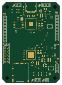
About the Rp569 PCB
Rp569 is an open source RP2040/RP2350 PCB design by kelu124, published on GitHub. It is a 4-layer board measuring 50 × 70 mm, with 142 components from 52 distinct parts.
Its main chip is the RP2350B, from the RP2040/RP2350 family. Other key parts include the TPD2EUSB30DRTR, TPS2121RUXR, AP2171WG-7, TLV62569DBVR and W25Q128JVSIQ. By type, the board carries 53 resistors, 51 capacitors, 12 ICs, 11 connectors, 7 switches and 4 inductors.
From the project
RP569 - PIOs to usb3 ( rp2350 x ch569 )
An open hardware board (KiCad) that pairs a Raspberry Pi RP2350B with a WCH CH569W. The RP2350B generates high-speed data and the CH569 streams it to a host over USB 3.0.
Status: v1.0 (tag v1.0). Schematic complete, PCB fully routed (4-layer, 50×70 mm, rounded corners, parts on both sides; 0 unconnected, 0 DRC errors) and JLCPCB production files generated. Before ordering: USB pairs as coupled pairs, silkscreen cleanup, impedance check (see docs/layout.md). First firmware for both chips in firmware/ (builds, not run on hardware yet). Schematic PDF. Documentation site…
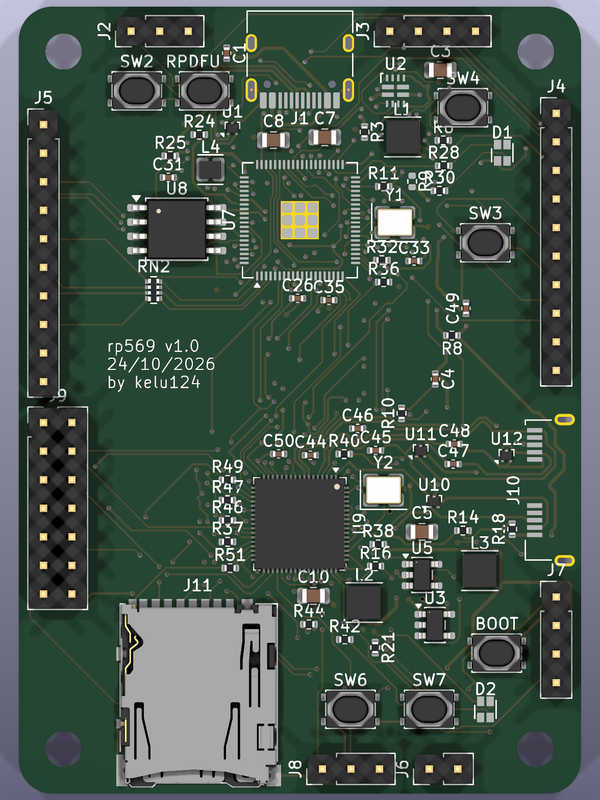
Main components on the Rp569
Rp569 bill of materials (BOM)
142 components, 52 distinct parts — part numbers from the project's BOM.
| Qty | Part | Footprint | Refs |
|---|---|---|---|
| 4 | TPD2EUSB30DRTR TPD2EUSB30 | Texas_DRT-3 | U1, U10, U11, U12 |
| 1 | TPS2121RUXR TPS2121 | TI_RUX0012A_VQFN-HR-12_2x2.5mm | U2 |
| 1 | AP2171WG-7 AP2171W | SOT-23-5 | U3 |
| 3 | TLV62569DBVR TLV62569 | SOT-23-5 | U4, U5, U6 |
| 1 | RP2350B | QFN-80-1EP_10x10mm_P0.4mm_EP3.4x3.4mm | U7 |
| 1 | W25Q128JVSIQ W25Q128JVS | SOIC-8_5.3x5.3mm_P1.27mm | U8 |
| 1 | CH569W | QFN-68-1EP_8x8mm_P0.4mm_EP5.2x5.2mm | U9 |
| 1 | ABM8-272-T3 12MHz | Crystal_SMD_3225-4Pin_3.2x2.5mm | Y1 |
| 1 | X322530MOB4SI 30MHz | Crystal_SMD_3225-4Pin_3.2x2.5mm | Y2 |
| 1 | TYPE-C-31-M-12 USB-C (RP2350) | USB_C_Receptacle_HRO_TYPE-C-31-M-12 | J1 |
| 1 | 2.54-1*3P SWD | PinHeader_1x03_P2.54mm_Vertical | J2 |
| 1 | PZ254V-11-04P RP I2C | PinHeader_1x04_P2.54mm_Vertical | J3 |
| 1 | PZ254V-11-10P RP EXT | PinHeader_1x10_P2.54mm_Vertical | J4 |
| 1 | PZ254V-11-10P LA IN | PinHeader_1x10_P2.54mm_Vertical | J5 |
| 1 | PZ254V-11-02P CH BOOT JP | PinHeader_1x02_P2.54mm_Vertical | J6 |
| 1 | PZ254V-11-04P CH I2C | PinHeader_1x04_P2.54mm_Vertical | J7 |
| 1 | 2.54-1*3P CH UART | PinHeader_1x03_P2.54mm_Vertical | J8 |
| 1 | PZ254V-12-14P CH EXT | PinHeader_2x07_P2.54mm_Vertical | J9 |
| 1 | GSB343K33HR USB3 Micro-B (CH569) | USB3_Micro-B_Amphenol_GSB343K33HR | J10 |
| 1 | DM3AT-SF-PEJM5 microSD | microSD_HC_Hirose_DM3AT-SF-PEJM5 | J11 |
Show 32 more
| Qty | Part | Footprint | Refs |
|---|---|---|---|
| 1 | PTS810SJG250SMTRLFS BOOTSEL | SW_SPST_PTS810 | SW1 |
| 1 | PTS810SJG250SMTRLFS RUN | SW_SPST_PTS810 | SW2 |
| 1 | PTS810SJG250SMTRLFS RP BTN1 | SW_SPST_PTS810 | SW3 |
| 1 | PTS810SJG250SMTRLFS RP BTN2 | SW_SPST_PTS810 | SW4 |
| 1 | PTS810SJG250SMTRLFS CH569 BOOT | SW_SPST_PTS810 | SW5 |
| 1 | PTS810SJG250SMTRLFS CH BTN1 | SW_SPST_PTS810 | SW6 |
| 1 | PTS810SJG250SMTRLFS CH BTN2 | SW_SPST_PTS810 | SW7 |
| 2 | LTST-C19HE1WT RGB | LED_LiteOn_LTST-C19HE1WT | D1, D2 |
| 3 | FTC303020D2R2MBCA 2.2uH | L_Changjiang_FTC303015D | L1, L2, L3 |
| 1 | AOTA-B201610S3R3-101-T 3.3uH | L_Cenker_CKCS201610 | L4 |
| 6 | CL05A475MP5NRNC 4.7uF | C_0402_1005Metric | C1, C29, C30, C31, C49, C51 |
| 1 | CL05B103KB5NNNC 10nF | C_0402_1005Metric | C2 |
| 6 | CL21A106KAYNNNE 10uF | C_0805_2012Metric | C3, C5, C6, C9, C12, C32 |
| 1 | CL05A105KA5NQNC 1uF | C_0402_1005Metric | C4 |
| 6 | CL21A226MAQNNNE 22uF | C_0805_2012Metric | C7, C8, C10, C11, C13, C14 |
| 27 | CL05B104KO5NNNC 100nF | C_0402_1005Metric | C15, C16, C17, C18, C19, C20, C21, C22 +19 |
| 4 | 0402CG150J500NT 15pF | C_0402_1005Metric | C33, C34, C45, C46 |
| 2 | 0402WGF5101TCE 5.1k | R_0402_1005Metric | R1, R2 |
| 2 | AC0402FR-0723K7L 23.7k | R_0402_1005Metric | R3, R5 |
| 2 | 0402WGF4991TCE 4.99k | R_0402_1005Metric | R4, R6 |
| 10 | 0402WGF1003TCE 100k | R_0402_1005Metric | R7, R10, R13, R15, R16, R17, R18, R20 +2 |
| 2 | 0402WGF0000TCE 0R | R_0402_1005Metric | R8, R9 |
| 7 | 0402WGF1002TCE 10k | R_0402_1005Metric | R11, R27, R33, R34, R37, R39, R40 |
| 2 | 0402WGF4533TCE 453k | R_0402_1005Metric | R12, R14 |
| 6 | 0402WGF4702TCE 47k | R_0402_1005Metric | R19, R46, R47, R48, R49, R50 |
| 1 | 0402WGF330JTCE 33R | R_0402_1005Metric | R22 |
| 3 | 0402WGF1001TCE 1k | R_0402_1005Metric | R23, R26, R38 |
| 2 | RC0402FR-0727RL 27R | R_0402_1005Metric | R24, R25 |
| 2 | 0402WGF3300TCE 330R | R_0402_1005Metric | R28, R41 |
| 4 | 0402WGF1000TCE 100R | R_0402_1005Metric | R29, R30, R42, R43 |
| 6 | 0402WGF4701TCE 4.7k | R_0402_1005Metric | R31, R32, R35, R36, R44, R45 |
| 2 | 4D02WGJ0101TCE 100R | R_Array_Convex_4x0402 | RN1, RN2 |
Rp569 design files
The KiCad project lives in the kelu124/rp569 repository on GitHub; these links point at the commit this page was built from.
Rp569: common questions
What microcontroller does the Rp569 use?
The Rp569 is built around the RP2350B, from the RP2040/RP2350 family.
How big is the Rp569 PCB?
The Rp569 measures 50 × 70 mm, has 4 copper layers and is 1.6 mm thick.
How many components are on the Rp569?
142 components, from 52 distinct parts, with part numbers taken from the project's own BOM. The full bill of materials is listed on this page.
Where can I download the Rp569 design files?
From the kelu124/rp569 repository on GitHub, which has the KiCad layout, the schematic and the BOM; the links under Design files point to each one.
Can I use the Rp569 design in my own project?
The repository has no license, so all rights stay with kelu124. Use it as a reference, and ask the author before reusing the design.
Can I test firmware for the Rp569 without the hardware?
Yes. HardLabs builds a simulation of the board from its netlist and BOM, so you can run and debug RP2040/RP2350 firmware against it before you order a PCB.
More boards in rp569
Similar boards
 RP2040/RP2350
OSO-BOOK-C1
joeycastillo
85 × 115 mm29 parts2LCC-BY-SA-4.08.1k RP2040/RP2350
Corne cherry
foostan
277.2 × 107.5 mm164 parts2LCC-BY-4.07.7k RP2040/RP2350
Corne chocolate
277.2 × 107.5 mm164 parts2LCC-BY-4.07.7k RP2040/RP2350
Jitx design
gusmanb
55.5 × 65 mm26 parts4LGPL-3.05.0k RP2040/RP2350
LogicAnalyzer
57 × 55.2 mm6 parts2LGPL-3.05.0k RP2040/RP2350
Main
google
98 × 71 mm102 parts2LApache-2.02.9k