
Leakwatch

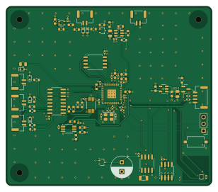
About the Leakwatch PCB
Leakwatch is an open source RP2040/RP2350 PCB design by lewipewi, published on GitHub. It is a 4-layer board measuring 77 × 67 mm, with 90 components from 43 distinct parts.
Its main chip is the RP2040, from the RP2040/RP2350 family. Other key parts include the DMG3415U-7, 74LVC1G14, TLV3011AIDBVT, CD4051B and OPA2333xxD. By type, the board carries 32 capacitors, 27 resistors, 12 ICs, 7 connectors, 2 crystals and 2 diodes.
It belongs with the sensors and robotics & motion designs in this gallery, and the repository also holds 1 earlier revision of it.
From the project
A multi-channel leak sensor for equipment enclosures. Instead of reporting "wet / dry" like a normal leak probe, it measures how wet each enclosure is, on a separate channel per enclosure, and carries a second circuit that raises an alarm in hardware with no firmware involved.
A multi-channel leak sensor for equipment enclosures. Instead of reporting "wet / dry" like a normal leak probe, it measures how wet each enclosure is, on a separate channel per enclosure, and carries a second circuit that raises an alarm in hardware with no firmware involved.
Designed with the Blue Robotics BlueROV2 in mind — a Navigator flight controller, I²C, and JST-GH connectors. The circuit itself is generic and would suit any multi-enclosure system.
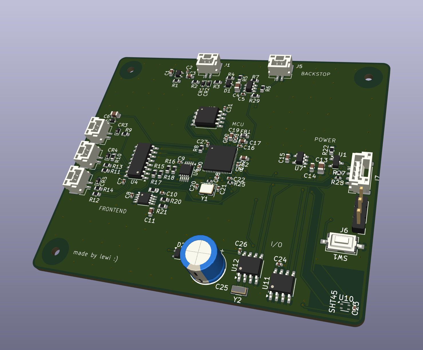
Main components on the Leakwatch
Leakwatch bill of materials (BOM)
90 components, 43 distinct parts.
| Qty | Part | Footprint | Refs |
|---|---|---|---|
| 1 | DMG3415U-7 | SOT-23 | U1 |
| 1 | 74LVC1G14 | SOT-353_SC-70-5 | U2 |
| 1 | TLV3011AIDBVT | SOT-23-6 | U3 |
| 1 | CD4051B | SOIC-16_3.9x9.9mm_P1.27mm | U4 |
| 1 | OPA2333xxD | MSOP-8_3x3mm_P0.65mm | U5 |
| 1 | TMUX1104DGSR | VSSOP-10_3x3mm_P0.5mm | U6 |
| 1 | AP2112K-3.3 | SOT-23-5 | U7 |
| 1 | RP2040 | QFN-56-1EP_7x7mm_P0.4mm_EP3.2x3.2mm | U8 |
| 1 | W25Q128JVSIQ | SOIC-8_5.3x5.3mm_P1.27mm | U9 |
| 1 | SHT45 | Sensirion_DFN-4_1.5x1.5mm_P0.8mm_SHT4x_NoCentralPad | U10 |
| 1 | MB85RC64 | SOIC-8_3.9x4.9mm_P1.27mm | U11 |
| 1 | PCF8563T | SOIC-8_3.9x4.9mm_P1.27mm | U12 |
| 1 | 12MHz | Crystal_SMD_3225-4Pin_3.2x2.5mm | Y1 |
| 1 | 32.768 kHz | Crystal_SMD_3215-2Pin_3.2x1.5mm | Y2 |
| 5 | Conn_01x02_Pin | JST_GH_BM02B-GHS-TBT_1x02-1MP_P1.25mm_Vertical | J1, J2, J3, J4, J5 |
| 1 | Conn_01x03_Pin | PinHeader_1x03_P2.54mm_Vertical | J6 |
| 1 | Conn_01x04_Pin | JST_GH_BM04B-GHS-TBT_1x04-1MP_P1.25mm_Vertical | J7 |
| 6 | PESD5V0S1BA | D_SOD-523 | CR1, CR2, CR3, CR4, CR5, CR6 |
| 1 | SW_Omron_B3FS | SW_Tactile_SPST_NO_Straight_CK_PTS636Sx25SMTRLFS | SW1 |
| 2 | BAT54W | SOT-323_SC-70 | D1, D2 |
Show 23 more
| Qty | Part | Footprint | Refs |
|---|---|---|---|
| 1 | 600R @ 100MHz | L_0603_1608Metric | FB1 |
| 1 | 4.7nF | C_0603_1608Metric | C1 |
| 16 | 100nF | C_0402_1005Metric | C2, C5, C7, C9, C10, C16, C18, C22 +8 |
| 6 | 1uF | C_0603_1608Metric | C3, C11, C14, C15, C17, C19 |
| 1 | 100nF | C_0805_2012Metric | C4 |
| 2 | 10uF | C_0805_2012Metric | C6, C13 |
| 1 | 2.2pF | C_0402_1005Metric | C8 |
| 1 | 1nF | C_0603_1608Metric | C12 |
| 3 | 15pF | C_0402_1005Metric | C20, C21, C31 |
| 1 | 0.1F | CP_Radial_D8.0mm_P3.50mm | C25 |
| 2 | 47k | R_0603_1608Metric | R1, R7 |
| 8 | 100 | R_0603_1608Metric | R2, R3, R8, R9, R10, R11, R12, R18 |
| 1 | 3.3k | R_0603_1608Metric | R4 |
| 2 | 1M | R_0603_1608Metric | R5, R13 |
| 1 | 2.2M | R_0603_1608Metric | R6 |
| 2 | 1k | R_0603_1608Metric | R14, R19 |
| 1 | 3M | R_0603_1608Metric | R15 |
| 2 | 100k | R_0603_1608Metric | R16, R22 |
| 1 | 3k | R_0603_1608Metric | R17 |
| 3 | 10k | R_0603_1608Metric | R20, R21, R29 |
| 1 | 1k | R_0402_1005Metric | R24 |
| 1 | 10k | R_0402_1005Metric | R25 |
| 2 | 4.7k | R_0402_1005Metric | R27, R28 |
Leakwatch design files
The KiCad project lives in the lewipewi/leakwatch repository on GitHub; these links point at the commit this page was built from.
Leakwatch: common questions
What microcontroller does the Leakwatch use?
The Leakwatch is built around the RP2040, from the RP2040/RP2350 family.
How big is the Leakwatch PCB?
The Leakwatch measures 77 × 67 mm, has 4 copper layers and is 1.6062 mm thick.
How many components are on the Leakwatch?
90 components, from 43 distinct parts. The full bill of materials is listed on this page.
Where can I download the Leakwatch design files?
From the lewipewi/leakwatch repository on GitHub, which has the KiCad layout; the links under Design files point to each one.
Can I use the Leakwatch design in my own project?
The repository has no license, so all rights stay with lewipewi. Use it as a reference, and ask the author before reusing the design.
Can I test firmware for the Leakwatch without the hardware?
Yes. HardLabs builds a simulation of the board from its netlist and BOM, so you can run and debug RP2040/RP2350 firmware against it before you order a PCB.
Earlier revisions in the repo: leak_sensor_v1
Similar boards
 RP2040/RP2350
Open Book Abridged Edition
joeycastillo
85 × 115 mm29 parts2LCC-BY-SA-4.08.1k RP2040/RP2350
Corne
foostan
277.2 × 107.5 mm164 parts2LCC-BY-4.07.7k RP2040/RP2350
Corne
277.2 × 107.5 mm164 parts2LCC-BY-4.07.7k RP2040/RP2350
LogicAnalyzer
gusmanb
57 × 55.2 mm6 parts2LGPL-3.05.0k RP2040/RP2350
Jitx design
55.5 × 65 mm26 parts4LGPL-3.05.0k RP2040/RP2350
Pro V2
kata0510
290.1 × 130 mm270 parts2LMIT2.3k