
Cell

About the Cell PCB
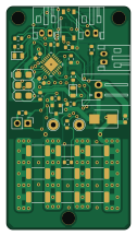
Cell is an open source AVR/Arduino PCB design by M-o-a-T, published on GitHub. It is a 2-layer board measuring 30 × 53.9 mm, with 36 components from 21 distinct parts.
Its main chip is the ATtiny827-MU, from the AVR/Arduino family. Other key parts include the PC817. By type, the board carries 22 resistors, 3 diodes, 2 ICs, 2 capacitors, 1 transistor and 1 fuse.
It belongs with the power & battery and iot & wireless designs in this gallery.
From the project
Schematics and files for MoaT IoT things
This directory contains schematics etc. pertaining to our BMS.
Instead of isoSPI or similar schemes that require specialized ICs, we use remote-powered digital isolators. This allows us to combine controllers as required.
All modules are connected in a loop. Communication can run both ways. Thus a single interrupted connection or wire will not hurt.
We always connect an OUT plug to an IN plug. Damage will result when two OUT sockets get connected. The same happens with two IN sockets.
Main components on the Cell
Cell bill of materials (BOM)
36 components, 21 distinct parts.
| Qty | Part | Footprint | Refs |
|---|---|---|---|
| 1 | PC817 | MFSOP6-4_4.4x3.6mm_P1.27mm | U1 |
| 1 | ATtiny827-MU | QFN-24-1EP_4x4mm_P0.5mm_EP2.6x2.6mm | U2 |
| 1 | Q_NMOS_20V_4A_lowVth | SOT-23 | Q1 |
| 3 | S2B-PH-K(LF)(SN) Conn_01x02_Male | JST_PH_S2B-PH-K_1x02_P2.00mm_Horizontal | EXTTEMP1, RX1, TX1 |
| 1 | MP005460 | Fuse_0603_1608Metric | F1 |
| 1 | Conn_01x02_Male | JST_XH_S2B-XH-A-1_1x02_P2.50mm_Horizontal | POWER1 |
| 1 | Conn_01x02_Male | PinHeader_1x02_P2.54mm_Vertical | REMOTE1 |
| 1 | SMBJ6.0CD-M3/H | D_SMB | D2 |
| 1 | LS R976 | LED_0805_2012Metric | D3 |
| 1 | LED KPTD-2012LVQBC-D | LED_0805_2012Metric | D4 |
| 1 | CC0805KRX7R9BB104 CP_100n_50V_0603 | C_0603_1608Metric | C1 |
| 1 | CP_1µ_10V_0603 | C_0603_1608Metric | C2 |
| 4 | R_10k_0603 | R_0603_1608Metric | R1, R3, R20, R21 |
| 3 | Rth_10k_SMD | R_0603_1608Metric | R2, R19, R23 |
| 1 | 0805W8F2200T5E R_220_0603 | R_0603_1608Metric | R5 |
| 9 | R_1_2W | R_2010_5025Metric | R6, R8, R12, R22, R24, R25, R26, R29 +1 |
| 1 | R_5k1_0603 | R_0603_1608Metric | R14 |
| 1 | 0805W8F1002T5E R_10k_0603 | R_0603_1608Metric | R15 |
| 1 | R_2k2_0603 | R_0603_1608Metric | R16 |
| 1 | 0805W8F2201T5E R_2k2_0603 | R_0603_1608Metric | R17 |
Show 1 more
| Qty | Part | Footprint | Refs |
|---|---|---|---|
| 1 | R_470_0603 | R_0603_1608Metric | R18 |
Cell design files
The KiCad project lives in the M-o-a-T/moat-hardware repository on GitHub; these links point at the commit this page was built from.
- Layoutbms/cell/cell.kicad_pcb
- Schematicbms/cell/cell.kicad_sch
Cell: common questions
What microcontroller does the Cell use?
The Cell is built around the ATtiny827-MU, from the AVR/Arduino family.
How big is the Cell PCB?
The Cell measures 30 × 53.9 mm, has 2 copper layers and is 1.6 mm thick.
How many components are on the Cell?
36 components, from 21 distinct parts. The full bill of materials is listed on this page.
Where can I download the Cell design files?
From the M-o-a-T/moat-hardware repository on GitHub, which has the KiCad layout and the schematic; the links under Design files point to each one.
Can I use the Cell design in my own project?
The repository has no license, so all rights stay with M-o-a-T. Use it as a reference, and ask the author before reusing the design.
Can I test firmware for the Cell without the hardware?
Yes. HardLabs builds a simulation of the board from its netlist and BOM, so you can run and debug AVR/Arduino firmware against it before you order a PCB.
More boards in moat-hardware
 RP2040/RP2350
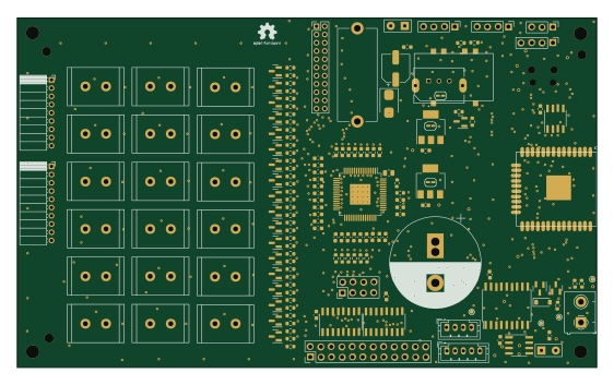
Base18
140.4 × 84.9 mm162 parts2LNo license0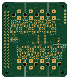 Raspberry Pi
PiPower
56 × 65 mm101 parts2LNo license0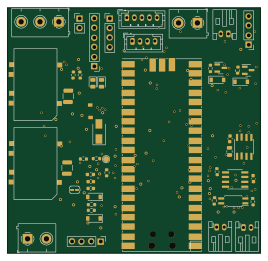 RP2040/RP2350
Ctrl
67 × 65 mm55 parts2LNo license0
Usb int
46.9 × 17.4 mm41 parts4LNo license0
Base heating
40.7 × 43.4 mm27 parts2LNo license0
Solvis control
54.4 × 45.9 mm22 parts2LNo license0
Enocean rs485
28.6 × 62 mm20 parts2LNo license0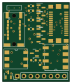
Base std
25.3 × 30 mm19 parts2LNo license0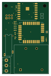 ESP8266
Enocean switch
43.3 × 67.3 mm18 parts2LNo license0 STM32
STM32Proc stm32
28 × 15.5 mm18 parts2LNo license0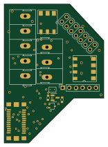
Base gira
38 × 53.2 mm18 parts2LNo license0
Similar boards
 AVR/Arduino
Redox keyboard
mattdibi
162.2 × 126.5 mm77 parts2LMIT2.0k AVR/Arduino
V4
stuartpittaway
30 × 50 mm38 parts2LCC-BY-NC-4.01.1k AVR/Arduino
ModuleV450
30 × 61.4 mm39 parts2LCC-BY-NC-4.01.1k AVR/Arduino
Discipline
coseyfannitutti
304.9 × 122.8 mm170 parts2LCC-BY-NC-4.01.0k AVR/Arduino
Megadesk
gcormier
41.7 × 32.2 mm23 parts2LGPL-3.0818 AVR/Arduino
Easyduino Atmega Nano
Hanqaqa
43.4 × 18 mm30 parts4LCERN-OHL-P-2.0746