
RGBW-Lampe

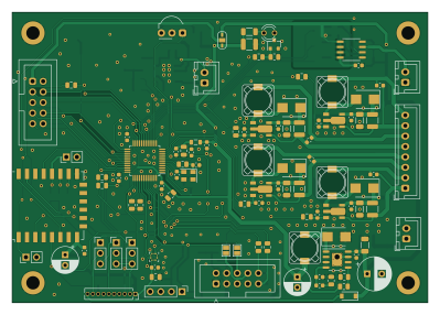
About the RGBW-Lampe PCB
RGBW-Lampe is an open source ESP8266 PCB design by martinclausen2, published on GitHub. It is a 2-layer board measuring 99.6 × 69.6 mm, with 155 components from 64 distinct parts.
Its main chip is the ESP-12F, from the ESP8266 family. Other key parts include the LIS2DH, L5973D, 24LC16, TSOP348xx and LM4861M. By type, the board carries 58 capacitors, 47 resistors, 12 ICs, 9 inductors, 8 connectors and 7 diodes.
It belongs with the iot & wireless and power & battery designs in this gallery.
From the project
The "RGBW-Lampe" projects allows to create full color lighting appliances.
The "RGBW-Lampe" projects allows to create full color lighting appliances.
- Four independent LED driver channels - Optimal to drive RGBW LED modules. - Mood light mode - High dynamic dimming range ideal for color mixing - Status LED to indicate power on, channel, standby, and network status - Brightness measurement to adjust brightness at power on - IR remote control (receiver and sender) - Option to network devices - Single rotational encoder and switch needed to control - Embedded terminal to control settings, clock, and alarms available via WLAN - Connect to home automation via MQTT -…
Main components on the RGBW-Lampe
RGBW-Lampe bill of materials (BOM)
155 components, 64 distinct parts.
| Qty | Part | Footprint | Refs |
|---|---|---|---|
| 1 | LIS2DH | LGA-14_2x2mm_P0.35mm_LayoutBorder3x4y | U1 |
| 1 | ESP-12F | ESP-12E | U2 |
| 1 | L5973D | HSOP-8-1EP_3.9x4.9mm_P1.27mm_EP2.41x3.1mm_ThermalVias | U3 |
| 1 | 24LC16 | SOIC-8_3.9x4.9mm_P1.27mm | U4 |
| 1 | TSOP348xx | Vishay_MOLD-3Pin | U5 |
| 1 | LM4861M | LM4861M | U6 |
| 1 | STM32L151CBTx | LQFP-48_7x7mm_P0.5mm | U7 |
| 1 | ISP762T | ISP762T | U8 |
| 4 | PT4115 | SOT89-5 | U$1, U$2, U$3, U$4 |
| 4 | BSS138 | SOT-23 | Q1, Q2, Q3, Q4 |
| 1 | 12MHz | Crystal_SMD_EuroQuartz_MT-4Pin_3.2x2.5mm | Y1 |
| 1 | 32,768 MS1V 7 | Crystal_SMD_MicroCrystal_MS1V-T1K | Y2 |
| 1 | Conn_01x10 | PinSocket_1x10_P1.27mm_Vertical | J1 |
| 1 | Conn_01x08 | JST_XH_B8B-XH-A_1x08_P2.50mm_Vertical | J3 |
| 3 | Conn_01x02 | JST_XH_B2B-XH-A_1x02_P2.50mm_Vertical | J4, J7, J8 |
| 1 | Conn_01x04_Male | PinHeader_1x04_P2.54mm_Vertical | J5 |
| 2 | Conn_02x05_Odd_Even | IDC-Header_2x05_P2.54mm_Vertical | J6, J9 |
| 3 | Jumper_3_Open | PinHeader_1x03_P2.54mm_Vertical | JP2, JP3, JP4 |
| 2 | Jumper_2_Open | PinHeader_1x02_P2.54mm_Vertical | JP5, JP6 |
| 1 | SFH320 | LED_PLCC-2 | T1 |
Show 44 more
| Qty | Part | Footprint | Refs |
|---|---|---|---|
| 1 | GM5WA94310A | GM5WA94310A | LED1 |
| 1 | SFH409 | LED3MM | LED2 |
| 5 | MBRS140 | D_SMB | D1, D2, D3, D4, D6 |
| 1 | SM6T18A | D_SMB | D5 |
| 1 | MBR0520 | D_SOD-123 | D7 |
| 4 | PIS2816 47µH | PIS2816 | L1, L2, L3, L4 |
| 2 | BLM31PG121 | L_1206_3216Metric | L5, L9 |
| 1 | PIS2816 15µH | PIS2816 | L6 |
| 2 | BLM21PG 331 | L_0805_2012Metric | L7, L8 |
| 1 | 100µF / 6.3V | C_1210_3225Metric | C1 |
| 18 | 220n | C_0603_1608Metric | C2, C9, C10, C12, C15, C19, C20, C21 +10 |
| 5 | 10µF / 25V | C_1206_3216Metric | C3, C7, C8, C13, C14 |
| 1 | 470µF / 25V | CP_Radial_D8.0mm_P3.50mm | C4 |
| 5 | 220nF / 25V | C_0603_1608Metric | C5, C17, C18, C48, C53 |
| 1 | 220p | C_0603_1608Metric | C6 |
| 1 | 22n | C_0603_1608Metric | C11 |
| 2 | 330µF / 6.3V | CP_Radial_D6.3mm_P2.50mm | C16, C28 |
| 2 | 22p | C_0603_1608Metric | C23, C24 |
| 2 | 4,3p | C_0603_1608Metric | C25, C27 |
| 5 | 1n | C_0603_1608Metric | C31, C32, C33, C49, C50 |
| 2 | 10µ | C_0805_2012Metric | C34, C51 |
| 2 | 1µF / 50V X7R | C_1206_3216Metric | C37, C46 |
| 1 | 1µ | C_0805_2012Metric | C39 |
| 4 | 100p | C_0603_1608Metric | C40, C41, C43, C44 |
| 1 | 100µF / 6,3V | C_1206_3216Metric | C47 |
| 5 | 10n | C_0603_1608Metric | C54, C55, C56, C57, C58 |
| 3 | 2,2k | R_0805_2012Metric | R1, R2, R4 |
| 1 | 4,7 | R_1206_3216Metric | R3 |
| 6 | 100 | R_0805_2012Metric | R5, R18, R22, R23, R32, R33 |
| 1 | 4.7k | R_0805_2012Metric | R6 |
| 4 | 0.150 | R_1210_3225Metric | R7, R8, R10, R11 |
| 1 | 5.6k | R_0805_2012Metric | R9 |
| 1 | 3.3k | R_0805_2012Metric | R12 |
| 1 | 10M | R_0805_2012Metric | R13 |
| 1 | 330k | R_0805_2012Metric | R14 |
| 11 | 10k | R_0805_2012Metric | R15, R24, R25, R26, R30, R31, R34, R35 +3 |
| 2 | 22k | R_0805_2012Metric | R16, R37 |
| 2 | 100k | R_0805_2012Metric | R17, R28 |
| 4 | 470 | R_0805_2012Metric | R19, R20, R21, R39 |
| 2 | 1k | R_0805_2012Metric | R27, R29 |
| 2 | 1.2k | R_0805_2012Metric | R38, R44 |
| 1 | 220k | R_0805_2012Metric | R40 |
| 1 | 180 | R_0805_2012Metric | R43 |
| 3 | ob | R_0805_2012Metric | R45, R46, R47 |
RGBW-Lampe design files
The KiCad project lives in the martinclausen2/RGBW-Lampe repository on GitHub; these links point at the commit this page was built from.
RGBW-Lampe: common questions
What microcontroller does the RGBW-Lampe use?
The RGBW-Lampe is built around the ESP-12F, from the ESP8266 family.
How big is the RGBW-Lampe PCB?
The RGBW-Lampe measures 99.6 × 69.6 mm, has 2 copper layers and is 1.6 mm thick.
How many components are on the RGBW-Lampe?
155 components, from 64 distinct parts. The full bill of materials is listed on this page.
Where can I download the RGBW-Lampe design files?
From the martinclausen2/RGBW-Lampe repository on GitHub, which has the KiCad layout and the schematic; the links under Design files point to each one.
Can I use the RGBW-Lampe design in my own project?
The repository has no license, so all rights stay with martinclausen2. Use it as a reference, and ask the author before reusing the design.
Can I test firmware for the RGBW-Lampe without the hardware?
Yes. HardLabs builds a simulation of the board from its netlist and BOM, so you can run and debug ESP8266 firmware against it before you order a PCB.
Similar boards
 ESP8266
ESP8266ControllerCircuit
stuartpittaway
75 × 30 mm20 parts2LCC-BY-NC-4.01.1k ESP8266
HASwitchPlate
aderusha
60 × 40 mm8 parts2LMIT738 ESP8266
Goatgdo
Kaldek
32.9 × 53.3 mm23 parts2LMIT506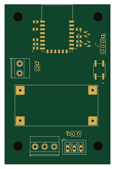 ESP8266
RatGDO-OpenSource-Bare-ESP8266
55 × 82.7 mm20 parts2LMIT506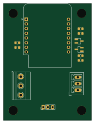 ESP8266
RatGDO-OpenSource-D1Mini-ESP8266
47.8 × 63.3 mm12 parts2LMIT506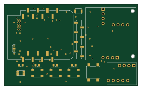 ESP8266
Iaq board
nkitanov
70.1 × 43.2 mm17 parts2LNo license398