
Smart room-Screen

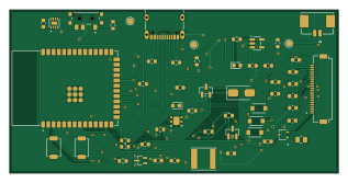
About the Smart room-Screen PCB
Smart room-Screen is an open source ESP32 PCB design by MohamadAminGhanoum, published on GitHub. It is a 2-layer board measuring 79.2 × 39.4 mm, with 53 components from 33 distinct parts.
Its main chip is the ESP32-S3-WROOM-1-N4, from the ESP32 family. Other key parts include the ADM803SAKSZ-REEL, ADP124ACPZ-3.3-R7, MCP73831-3-OT and HTU21D. By type, the board carries 17 capacitors, 16 resistors, 5 ICs, 3 connectors, 3 switches and 3 diodes.
It belongs with the displays & leds, sensors and iot & wireless designs in this gallery.
From the project
Since i made a previous project about automating my room to control, e.g led strip, open/close the curtain and also measure temperature in the room, im thinking about making a display e-ink mb and make it show me the weather when i wake up, so i do not have to stare into my phone, but i would also like it to show me the time.
When i usually wake up, i usually look on my phone screen to see the clock, and then i open my social media and do other stuff, which i honestly want to prevent. Therefore i have thought to make a e-ink display on the table next to me, so that i can see the clock and weather directly from my bed when i turn on my night light.
Since i made a previous project about automating my room to control, e.g led strip, open/close the curtain and also measure temperature in the room, i am thinking that i can make this hang together with my other smart-home project.
Main components on the Smart room-Screen
Smart room-Screen bill of materials (BOM)
53 components, 33 distinct parts — part numbers from the project's BOM.
| Qty | Part | Footprint | Refs |
|---|---|---|---|
| 1 | ADM803SAKSZ-REEL | SOT65P210X110-3N | U1 |
| 1 | ADP124ACPZ-3.3-R7 | SON50P200X200X60-9N | U3 |
| 1 | MCP73831-3-OT | SOT-23-5 | U4 |
| 1 | HTU21D | QFN100P300X300X100-7N | U5 |
| 1 | ESP32-S3-WROOM-1-N4 | XCVR_ESP32-S3-WROOM-1-N4 | U6 |
| 2 | AO3401A | SOT-23 | Q1, Q2 |
| 1 | USB_C_RECEPTACLE_USB2.0_14P USB_C_Receptacle_USB2.0_14P | USB_C_Receptacle_XKB_U262-16XN-4BVC11 | J1 |
| 1 | battery connector | MOLEX_532610271 | J2 |
| 1 | F34G-1A7Q1-E8C24 | AMPHENOL_F34G-1A7Q1-E8C24 | J3 |
| 3 | SS2040FL_R1_00001 | CR_R1_00001_PNJ | CR1, CR2, CR3 |
| 1 | SLW-66527511-SMT SLW-66527511-SMT-TR | SW_SLW-66527511-SMT-TR | S1 |
| 1 | boot | SW_SPST_TS-1088-xR020 | SW1 |
| 1 | reset | SW_SPST_TS-1088-xR020 | SW2 |
| 1 | SS14 | D_SMA | D1 |
| 2 | LED | LED_0603_1608Metric | D2, D3 |
| 1 | 10UH 10uH | L_Taiyo-Yuden_MD-4040 | L1 |
| 2 | 10UF 10uF | C_0603_1608Metric | C1, C2 |
| 1 | 4.7UF 4.7uF | C_0603_1608Metric | C3 |
| 1 | 10UF 10 uF | C_0603_1608Metric | C4 |
| 4 | 100NF 100nF | C_0603_1608Metric | C5, C6, C7, C16 |
Show 13 more
| Qty | Part | Footprint | Refs |
|---|---|---|---|
| 7 | 4.7uF, 25V | C_0603_1608Metric | C8, C9, C10, C11, C12, C13, C15 |
| 2 | 4.7uF,25V | C_0603_1608Metric | C14, C17 |
| 2 | 5.1K | R_0603_1608Metric | R1, R2 |
| 1 | 100K | R_0603_1608Metric | R3 |
| 3 | 10K | R_0603_1608Metric | R4, R10, R13 |
| 1 | 3K | R_0603_1608Metric | R5 |
| 1 | 470 | R_0603_1608Metric | R6 |
| 2 | 4.7K | R_0603_1608Metric | R7, R8 |
| 1 | RTF025N03TL | SOT-323T_ROM | R9 |
| 2 | 33R | R_0603_1608Metric | R11, R12 |
| 1 | 0.47R | R_0805_2012Metric | R14 |
| 1 | 47K | R_0603_1608Metric | R15 |
| 1 | 1K | R_0603_1608Metric | R16 |
Smart room-Screen design files
The KiCad project lives in the MohamadAminGhanoum/Smart-room-Screen repository on GitHub; these links point at the commit this page was built from.
Smart room-Screen: common questions
What microcontroller does the Smart room-Screen use?
The Smart room-Screen is built around the ESP32-S3-WROOM-1-N4, from the ESP32 family.
How big is the Smart room-Screen PCB?
The Smart room-Screen measures 79.2 × 39.4 mm, has 2 copper layers and is 1.6 mm thick.
How many components are on the Smart room-Screen?
53 components, from 33 distinct parts, with part numbers taken from the project's own BOM. The full bill of materials is listed on this page.
Where can I download the Smart room-Screen design files?
From the MohamadAminGhanoum/Smart-room-Screen repository on GitHub, which has the KiCad layout, the schematic and the BOM; the links under Design files point to each one.
Can I use the Smart room-Screen design in my own project?
The repository has no license, so all rights stay with MohamadAminGhanoum. Use it as a reference, and ask the author before reusing the design.
Can I test firmware for the Smart room-Screen without the hardware?
Yes. HardLabs builds a simulation of the board from its netlist and BOM, so you can run and debug ESP32 firmware against it before you order a PCB.
Similar boards
 ESP32
OSO-BOOK-B1
joeycastillo
85 × 115 mm65 parts2LCC-BY-SA-4.08.1k ESP32
Powertrain
byrantech
64 × 45.4 mm171 parts4LMIT4.3k ESP32
Badge
atopile
56.3 × 39 mm239 parts4LMIT4.0k ESP32
Esp32 minimal
36.2 × 26.8 mm20 parts2LMIT4.0k ESP32
Racer
StuckAtPrototype
36 × 50.2 mm70 parts4LApache-2.03.8k ESP32
Controller
29 × 74 mm58 parts4LApache-2.03.8k