
Power subsystem

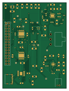
About the Power subsystem PCB
Power subsystem is an open source PCB design by MTHSEK006, published on GitHub. It is a 2-layer board measuring 59.3 × 80.4 mm, with 71 components from 33 distinct parts.
Other key parts include the CH224K, TPS61088RHLR, TPS63802DLAR, DRV8833PWPR and INA219AIDCNR. By type, the board carries 31 resistors, 26 capacitors, 9 ICs, 2 inductors, 1 connector and 1 switch.
It belongs with the power & battery designs in this gallery.
From the project
Power subsystem PCB design using kicad
EEE3088 Power Sub-system Project MTHSEK006 & MKFMOR011
This project involves the design and development of the micro-mouse power sub-system. The power sub-system is used to power the entire micro-mouse. This project is designed and developed in Kicad. Production files are jlcpcb compatible because project PCB is developed by JLCPCB. There are eight requirements in total. These requirements will be equally divided between MTHSEK006 and MFKMOR011. MTHSEK006 requirements designs can be found under pearlpcbdesign branch and MFKMOR011 requirements design can be found under morenapcbdesign branch.…
Main components on the Power subsystem
Power subsystem bill of materials (BOM)
71 components, 33 distinct parts — part numbers from the project's BOM.
| Qty | Part | Footprint | Refs |
|---|---|---|---|
| 1 | CH224K | SOP100P600X180-11N | IC1 |
| 1 | TPS61088RHLR | RHL(R-PVQFN-N20)_1 | IC2 |
| 1 | TPS63802DLAR | TPS63802DLAR | IC3 |
| 2 | DRV8833PWPR | HTSSOP-16-1EP_4.4x5mm_P0.65mm_EP3.4x5mm_Mask2.46x2.31mm | U1, U2 |
| 1 | INA219AIDCNR | SOT65P280X145-8N | U3 |
| 2 | SIP32431DNP3-T1GE4 | SON50P120X160X60-5N | U4, U5 |
| 1 | BQ24074RGT | QFN50P300X300X100-17N-D | U6 |
| 1 | C393939 USB Type C | SHOUHAN_TYPE-C_16PIN_2MD__073_ | J2 |
| 1 | TestPoint | TestPoint_THTPad_1.0x1.0mm_Drill0.5mm | MCUTP1 |
| 1 | SS-12D06-G030 | SS-12D06_GSW | SW1 |
| 1 | 1.2UH 1.2uH | L_0603_1608Metric_Pad1.05x0.95mm_HandSolder | L1 |
| 1 | 0.47UH 0.47uH | L_0603_1608Metric_Pad1.05x0.95mm_HandSolder | L2 |
| 6 | 10UF 10uF | C_1206_3216Metric_Pad1.33x1.80mm_HandSolder | C1, C2, C6, C13, C14, C25 |
| 5 | 1UF 1uF | C_1206_3216Metric_Pad1.33x1.80mm_HandSolder | C3, C7, C8, C9, C10 |
| 2 | 0.01UF 0.01uF | C_0805_2012Metric_Pad1.18x1.45mm_HandSolder | C4, C12 |
| 3 | 2.2UF 2.2uF | C_0603_1608Metric_Pad1.08x0.95mm_HandSolder | C5, C11, C21 |
| 5 | 22UF 22uF | C_1206_3216Metric_Pad1.33x1.80mm_HandSolder | C15, C16, C18, C19, C26 |
| 1 | 470PF 470pF | C_0603_1608Metric_Pad1.08x0.95mm_HandSolder | C17 |
| 1 | 22UF 1uF | C_1206_3216Metric_Pad1.33x1.80mm_HandSolder | C20 |
| 1 | 47NF 47nF | C_0603_1608Metric_Pad1.08x0.95mm_HandSolder | C22 |
Show 13 more
| Qty | Part | Footprint | Refs |
|---|---|---|---|
| 2 | 0.1UF 0.1uF | C_0402_1005Metric_Pad0.74x0.62mm_HandSolder | C23, C24 |
| 6 | 10K 10k | R_0805_2012Metric_Pad1.20x1.40mm_HandSolder | R2, R6, R10, R15, R17, R33 |
| 6 | 1 | R_1206_3216Metric_Pad1.30x1.75mm_HandSolder | R3, R28, R29, R30, R31, R32 |
| 2 | 4.7K | R_1206_3216Metric_Pad1.30x1.75mm_HandSolder | R5, R8 |
| 5 | 1k | R_1206_3216Metric_Pad1.30x1.75mm_HandSolder | R7, R13, R14, R16, R18 |
| 1 | 6.8K 6.8k | R_0805_2012Metric_Pad1.20x1.40mm_HandSolder | R9 |
| 1 | 18K | R_0603_1608Metric_Pad0.98x0.95mm_HandSolder | R11 |
| 1 | 1.8K 1.8k | R_0603_1608Metric_Pad0.98x0.95mm_HandSolder | R12 |
| 1 | 47K 47k | R_0805_2012Metric_Pad1.20x1.40mm_HandSolder | R19 |
| 1 | 511K 511k | R_0603_1608Metric_Pad0.98x0.95mm_HandSolder | R20 |
| 5 | 100K 100k | R_0402_1005Metric_Pad0.72x0.64mm_HandSolder | R21, R22, R23, R25, R27 |
| 1 | 255K 255k | R_0402_1005Metric_Pad0.72x0.64mm_HandSolder | R24 |
| 1 | 120K 120k | R_0603_1608Metric_Pad0.98x0.95mm_HandSolder | R26 |
Power subsystem design files
The KiCad project lives in the MTHSEK006/Power-subsystem-PCB repository on GitHub; these links point at the commit this page was built from.
Power subsystem: common questions
How big is the Power subsystem PCB?
The Power subsystem measures 59.3 × 80.4 mm, has 2 copper layers and is 1.6 mm thick.
How many components are on the Power subsystem?
71 components, from 33 distinct parts, with part numbers taken from the project's own BOM. The full bill of materials is listed on this page.
Where can I download the Power subsystem design files?
From the MTHSEK006/Power-subsystem-PCB repository on GitHub, which has the KiCad layout, the schematic and the BOM; the links under Design files point to each one.
Can I use the Power subsystem design in my own project?
The repository has no license, so all rights stay with MTHSEK006. Use it as a reference, and ask the author before reusing the design.
Similar boards

EinkPDA screen
TalismanDesign
95 × 54 mm27 parts2LApache-2.02.0k
Stack chan
stack-chan
50 × 50 mm33 parts2LApache-2.01.7k
Display Carrier
AxxAxx
35.6 × 58.2 mm5 parts2LGPL-3.01.7k
ProgrammingAdapter
stuartpittaway
10.5 × 83 mm3 parts2LCC-BY-NC-4.01.1k
TemperaturePCB PANEL
116 × 75.5 mm178 parts2LCC-BY-NC-4.01.1k
Module 16S PassiveBalanceAddOn
61 × 74 mm86 parts2LCC-BY-NC-4.01.1k