
ATE-PCB-DESIGN

About the ATE-PCB-DESIGN
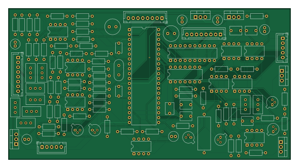
ATE-PCB-DESIGN is an open source PIC PCB design by muhin19, published on GitHub. It is a 2-layer board measuring 147 × 78.5 mm, with 110 components from 49 distinct parts.
Its main chip is the DSPIC30F4011-30I/P, from the PIC family. Other key parts include the LF353, LM7905, L7809, L7805 and 74LS244. By type, the board carries 64 resistors, 17 capacitors, 15 ICs, 8 transistors, 5 connectors and 1 crystal.
From the project
PCB design for an Automatic Test Equipment (ATE) system, including circuit design, component placement, routing, and PCB layout for electronic testing applications.
📌 Project Overview This project involves the design and development of a Printed Circuit Board (PCB) for an Automatic Test Equipment (ATE) application. It includes PCB layout design, component placement, track routing, and design verification to achieve a reliable and organized hardware layout.
🎯 Objectives Design a PCB layout for an ATE application. Arrange electronic components efficiently. Route signal and power connections properly. Maintain a clear and organized PCB layout. Prepare PCB design files for manufacturing and further testing.
Main components on the ATE-PCB-DESIGN
ATE-PCB-DESIGN bill of materials (BOM)
110 components, 49 distinct parts — part numbers from the project's BOM.
| Qty | Part | Footprint | Refs |
|---|---|---|---|
| 3 | LF353 | DIP-8_W7.62mm | U1, U7, U12 |
| 1 | LM7905 | TO-220-3_Vertical | U2 |
| 1 | L7809 | TO-220-3_Vertical | U3 |
| 1 | L7805 | TO-220-3_Vertical | U4 |
| 1 | 74LS244 | DIP-20_W7.62mm | U5 |
| 1 | DSPIC30F4011-30I/P | DIP-40_W15.24mm | U6 |
| 1 | LF357 | DIP-8_W7.62mm | U8 |
| 3 | LF398 | DIP-8_W7.62mm | U9, U11, U15 |
| 1 | CD40106B | DIP-14_W7.62mm | U13 |
| 1 | LF535 | DIP-8_W7.62mm | U14 |
| 1 | LM311 | DIP-8_W7.62mm | U16 |
| 1 | 2N5294 | TO-220-3_Vertical | Q1 |
| 3 | BC107 | TO-18-3 | Q2, Q5, Q7 |
| 3 | BC177 | TO-18-3 | Q3, Q6, Q8 |
| 1 | 2N6107 | TO-220-3_Vertical | Q4 |
| 1 | 6MHZ 6MHz | Crystal_HC49-U_Vertical | Y1 |
| 1 | ANALOG IN | JST_XH_B8B-XH-A_1x08_P2.50mm_Vertical | CON1 |
| 1 | D IO | JST_XH_B8B-XH-A_1x08_P2.50mm_Vertical | CON2 |
| 1 | POWER IN | JST_XH_B8B-XH-A_1x08_P2.50mm_Vertical | CON3 |
| 1 | ANALOG OP | JST_XH_B5B-XH-A_1x05_P2.50mm_Vertical | CON4 |
Show 29 more
| Qty | Part | Footprint | Refs |
|---|---|---|---|
| 1 | RS232 | JST_XH_B5B-XH-A_1x05_P2.50mm_Vertical | CON5 |
| 3 | 47UF 25V | C_Radial_D5.0mm_H11.0mm_P2.00mm | C1, C2, C3 |
| 1 | 25UF 25V | C_Radial_D5.0mm_H11.0mm_P2.00mm | C4 |
| 1 | 0.1UF | C_Radial_D5.0mm_H11.0mm_P2.00mm | C5 |
| 2 | 22PF | C_Disc_D5.1mm_W3.2mm_P5.00mm | C6, C7 |
| 4 | 680PF | C_Disc_D6.0mm_W4.4mm_P5.00mm | C8, C9, C10, C12 |
| 2 | 1800PF | C_Disc_D6.0mm_W4.4mm_P5.00mm | C11, C13 |
| 1 | 1UF 16V | C_Radial_D5.0mm_H11.0mm_P2.00mm | C14 |
| 1 | 0.01UF | C_Axial_L17.0mm_D6.5mm_P20.00mm_Horizontal | C15 |
| 2 | 220UF 25V | C_Radial_D8.0mm_H11.5mm_P3.50mm | C16, C18 |
| 2 | 1K | Potentiometer_Bourns_3296W_Vertical | R1, R59 |
| 6 | 50K | Potentiometer_Bourns_3296W_Vertical | R2, R11, R17, R27, R35, R44 |
| 6 | 820K | R_Axial_DIN0207_L6.3mm_D2.5mm_P10.16mm_Horizontal | R3, R12, R18, R28, R36, R45 |
| 7 | 4.7K | R_Axial_DIN0207_L6.3mm_D2.5mm_P10.16mm_Horizontal | R4, R13, R19, R30, R37, R47, R60 |
| 1 | 10 | R_Axial_DIN0207_L6.3mm_D2.5mm_P10.16mm_Horizontal | R5 |
| 6 | 120K | R_Axial_DIN0207_L6.3mm_D2.5mm_P10.16mm_Horizontal | R6, R14, R20, R31, R38, R48 |
| 3 | 10K | R_Axial_DIN0207_L6.3mm_D2.5mm_P10.16mm_Horizontal | R7, R57, R65 |
| 12 | 100K | R_Axial_DIN0207_L6.3mm_D2.5mm_P10.16mm_Horizontal | R8, R9, R15, R16, R22, R23, R32, R33 +4 |
| 1 | 560 | R_Axial_DIN0207_L6.3mm_D2.5mm_P10.16mm_Horizontal | R10 |
| 2 | 1 | R_Axial_DIN0207_L6.3mm_D2.5mm_P10.16mm_Horizontal | R21, R25 |
| 4 | 5.6K | R_Axial_DIN0207_L6.3mm_D2.5mm_P10.16mm_Horizontal | R24, R26, R34, R50 |
| 3 | 1.8K | R_Axial_DIN0207_L6.3mm_D2.5mm_P10.16mm_Horizontal | R29, R39, R53 |
| 1 | 2.7K | R_Axial_DIN0207_L6.3mm_D2.5mm_P10.16mm_Horizontal | R42 |
| 1 | 56K | R_Axial_DIN0207_L6.3mm_D2.5mm_P10.16mm_Horizontal | R46 |
| 2 | 18K | R_Axial_DIN0207_L6.3mm_D2.5mm_P10.16mm_Horizontal | R49, R62 |
| 1 | 470 | R_Axial_DIN0207_L6.3mm_D2.5mm_P10.16mm_Horizontal | R51 |
| 1 | 10K | Potentiometer_Bourns_3296W_Vertical | R52 |
| 2 | 5.1K | R_Axial_DIN0207_L6.3mm_D2.5mm_P10.16mm_Horizontal | R54, R58 |
| 3 | 1K | R_Axial_DIN0207_L6.3mm_D2.5mm_P10.16mm_Horizontal | R61, R63, R64 |
ATE-PCB-DESIGN design files
The KiCad project lives in the muhin19/ATE-PCB-DESIGN repository on GitHub; these links point at the commit this page was built from.
- LayoutPCB Layout.kicad_pcb
- BOMBOM.csv
ATE-PCB-DESIGN: common questions
What microcontroller does the ATE-PCB-DESIGN use?
The ATE-PCB-DESIGN is built around the DSPIC30F4011-30I/P, from the PIC family.
How big is the ATE-PCB-DESIGN?
The ATE-PCB-DESIGN measures 147 × 78.5 mm, has 2 copper layers and is 1.6 mm thick.
How many components are on the ATE-PCB-DESIGN?
110 components, from 49 distinct parts, with part numbers taken from the project's own BOM. The full bill of materials is listed on this page.
Where can I download the ATE-PCB-DESIGN design files?
From the muhin19/ATE-PCB-DESIGN repository on GitHub, which has the KiCad layout and the BOM; the links under Design files point to each one.
Can I use the ATE-PCB-DESIGN design in my own project?
The repository has no license, so all rights stay with muhin19. Use it as a reference, and ask the author before reusing the design.
Can I test firmware for the ATE-PCB-DESIGN without the hardware?
Yes. HardLabs builds a simulation of the board from its netlist and BOM, so you can run and debug PIC firmware against it before you order a PCB.
Similar boards
 PIC
Pslab hardware
fossasia
99 × 53.3 mm187 parts4LApache-2.01.7k PIC
Lens
ervanalb
80 × 80 mm53 parts4LNo license515 PIC
Micro 8088
skiselev
152.4 × 101.6 mm71 partsGPL-3.0414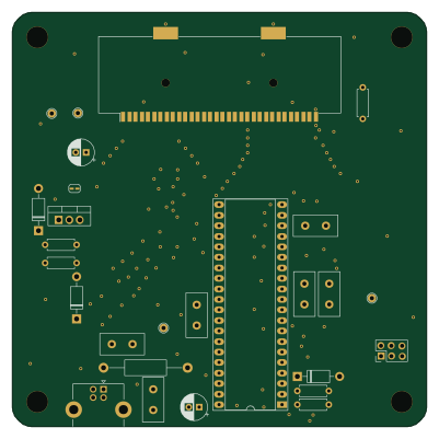 PIC
GB-CARTPP-DIY
Gekkio
100 × 100 mm22 parts2LCC-BY-4.0379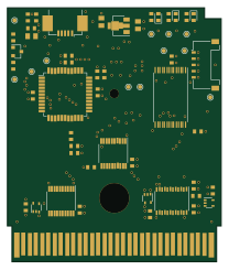 PIC
GB-LIVE32
51.4 × 61 mm46 parts4LCC-BY-4.0379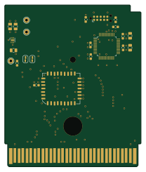 PIC
GB-CART256K-A
51.4 × 61 mm17 parts2LCC-BY-4.0379