
Greybadge25

About the Greybadge25 PCB
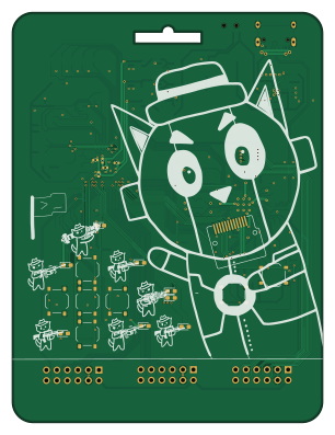
Greybadge25 is an open source RP2040/RP2350 PCB design by NUSGreyhats, published on GitHub. It is a 2-layer board measuring 75 × 99 mm, with 126 components from 46 distinct parts.
Its main chip is the RP2350_60QFN, from the RP2040/RP2350 family. Other key parts include the TLV73311PDBV, TLV73325PDBV, GC9A01_IPS_display, BQ24075 and W25Q128JVS. By type, the board carries 42 resistors, 40 capacitors, 11 diodes, 10 switches, 9 ICs and 5 connectors.
It belongs with the wearables, power & battery and usb & debug tools designs in this gallery.
From the project
GreyMecha/Army GreyCTF 2025 Badge
1. Instruction Manual 2. Slides for Badge Talk
To view the schematic, find the pcb/prototype3 release and get the schematic pdf from there
Feel free to update the BOM to remove the oscillator for the FPGA as it is expensive and not strictly necessary.
Ordering on JLCPCB: 1. Upload the GERBER into the order page. 2. For the PCB Fab options, we recommend mostly using the defaults, but keep the following options in mind: - Finishing: HASL (HASL is fine, though we recommend ENIG for higher quantities as the extra cost scales well and is better for BGA soldering.) - To customize the main PCB…
Main components on the Greybadge25
Greybadge25 bill of materials (BOM)
126 components, 46 distinct parts.
| Qty | Part | Footprint | Refs |
|---|---|---|---|
| 1 | TLV73311PDBV | SOT-23-5 | U2 |
| 1 | TLV73325PDBV | SOT-23-5 | U3 |
| 1 | GC9A01_IPS_display | GC9A01_IPS_display | U4 |
| 1 | BQ24075 | VQFN-16-1EP_3x3mm_P0.5mm_EP1.6x1.6mm | U5 |
| 1 | W25Q128JVS | SOIC-8_5.3x5.3mm_P1.27mm | U6 |
| 1 | RP2350_60QFN | RP2350-QFN-60-1EP_7x7_P0.4mm_EP3.4x3.4mm_ThermalVias | U7 |
| 1 | ECP5U_25_CABGA256 | BGA-256_14.0x14.0mm_Layout16x16_P0.8mm_Ball0.45mm_Pad0.32mm_NSMD | U8 |
| 1 | W25Q128JVSIM | SOIC-8_5.3x5.3mm_P1.27mm | U9 |
| 1 | AMS1117-3.3 | SOT-89-3_L4.5-W2.5-P1.50-LS4.2-BR | U10 |
| 1 | 2N7002 | SOT-23 | Q1 |
| 1 | Q_NMOS_GSD | SOT-23 | Q2 |
| 1 | SiT2001B | SOT-23-5 | X1 |
| 1 | 12Mhz | Crystal_SMD_3225-4Pin_3.2x2.5mm | Y1 |
| 3 | Conn_02x05_Row_Letter_First | PinSocket_2x06_P2.54mm_Horizontal | J1, J2, J3 |
| 1 | JST PH S2B | JST_PH_S2B-PH-SM4-TB_1x02-1MP_P2.00mm_Horizontal | J4 |
| 1 | USB_C_Receptacle_USB2.0 | USB_C_Receptacle_HRO_TYPE-C-31-M-12 | J5 |
| 1 | Buzzer | BUZ-SMD_4P-L7.5-W7.5-BR | BZ1 |
| 9 | SW_Push | SW_Push_1P1T_XKB_TS-1187A | SW1, SW2, SW3, SW4, SW5, SW6, SW7, SW9 +1 |
| 1 | SW_SPDT | SW_SPDT_PCM12 | SW8 |
| 8 | LED | LED_0603_1608Metric_Pad1.05x0.95mm_HandSolder | D1, D2, D3, D4, D5, D6, D7, D8 |
Show 26 more
| Qty | Part | Footprint | Refs |
|---|---|---|---|
| 2 | LED | LED_0805_2012Metric | D9, D11 |
| 1 | SS14 | D_SOD-123 | D10 |
| 3 | Ferrite_Bead_Small | L_0805_2012Metric | FB1, FB2, FB3 |
| 1 | 3.3u | L_pol_2016 | L3 |
| 6 | 4.7u | C_0402_1005Metric | C1, C3, C27, C28, C29, C40 |
| 19 | 100n | C_0402_1005Metric | C5, C6, C7, C9, C10, C15, C18, C26 +11 |
| 3 | 10u | C_0402_1005Metric | C8, C11, C16 |
| 6 | 1u | C_0402_1005Metric | C12, C13, C17, C21, C23, C25 |
| 4 | 4u7 | C_0402_1005Metric | C19, C20, C22, C24 |
| 2 | 22pF | C_0402_1005Metric | C30, C31 |
| 16 | 10k | R_0603_1608Metric_Pad0.98x0.95mm_HandSolder | R1, R3, R6, R8, R9, R10, R13, R38 +8 |
| 8 | 470 | R_0603_1608Metric_Pad0.98x0.95mm_HandSolder | R2, R4, R5, R7, R11, R12, R14, R15 |
| 1 | 1k | R_0805_2012Metric | R20 |
| 1 | 22 | R_0603_1608Metric | R21 |
| 1 | 10k | R_0603_1608Metric | R22 |
| 1 | 10k | R_0402_1005Metric | R23 |
| 1 | 47k | R_0402_1005Metric | R24 |
| 1 | 1k5 | R_0402_1005Metric | R25 |
| 1 | 2k2 | R_0402_1005Metric | R26 |
| 1 | 33 | R_0402_1005Metric | R27 |
| 1 | DNF | R_0402_1005Metric | R28 |
| 1 | 0 | R_0402_1005Metric | R29 |
| 2 | 27R | R_0402_1005Metric | R30, R31 |
| 3 | 1k | R_0402_1005Metric | R32, R33, R34 |
| 2 | 5k1 | R_0402_1005Metric | R35, R36 |
| 1 | 200R | R_0805_2012Metric | R37 |
Greybadge25 design files
The KiCad project lives in the NUSGreyhats/greybadge25 repository on GitHub; these links point at the commit this page was built from.
Greybadge25: common questions
What microcontroller does the Greybadge25 use?
The Greybadge25 is built around the RP2350_60QFN, from the RP2040/RP2350 family.
How big is the Greybadge25 PCB?
The Greybadge25 measures 75 × 99 mm, has 2 copper layers and is 1.6 mm thick.
How many components are on the Greybadge25?
126 components, from 46 distinct parts. The full bill of materials is listed on this page.
Where can I download the Greybadge25 design files?
From the NUSGreyhats/greybadge25 repository on GitHub, which has the KiCad layout and the schematic; the links under Design files point to each one.
Can I use the Greybadge25 design in my own project?
The repository has no license, so all rights stay with NUSGreyhats. Use it as a reference, and ask the author before reusing the design.
Can I test firmware for the Greybadge25 without the hardware?
Yes. HardLabs builds a simulation of the board from its netlist and BOM, so you can run and debug RP2040/RP2350 firmware against it before you order a PCB.
Similar boards
 RP2040/RP2350
Open Book Abridged Edition
joeycastillo
85 × 115 mm29 parts2LCC-BY-SA-4.08.1k RP2040/RP2350
Corne
foostan
277.2 × 107.5 mm164 parts2LCC-BY-4.07.7k RP2040/RP2350
Corne
277.2 × 107.5 mm164 parts2LCC-BY-4.07.7k RP2040/RP2350
Jitx design
gusmanb
55.5 × 65 mm26 parts4LGPL-3.05.0k RP2040/RP2350
LogicAnalyzer
57 × 55.2 mm6 parts2LGPL-3.05.0k RP2040/RP2350
Main
google
98 × 71 mm102 parts2LApache-2.02.9k