
R7

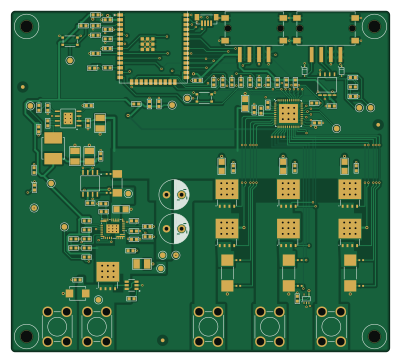
About the R7 PCB
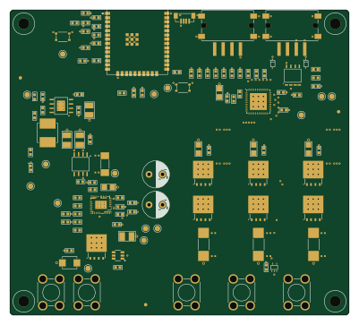
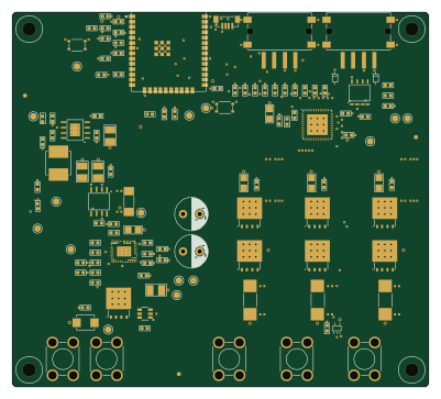
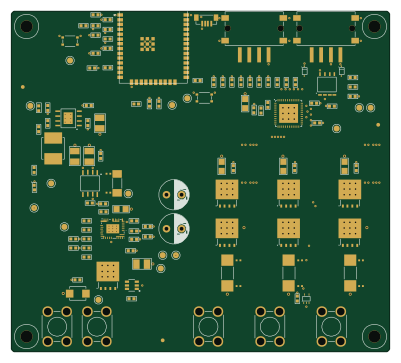
R7 is an open source ESP32 PCB design by odtu, published on GitHub under the CERN-OHL-S-2.0 license. It is a 4-layer board measuring 100 × 90 mm, with 109 components from 52 distinct parts.
Its main chip is the ESP32-WROOM-32E, from the ESP32 family. Other key parts include the LM74700QDBVRQ1, PTPS16890VMAR, LMR38020FSDDAR, DRV8323RSRGZT and TMP235A4DCKR. By type, the board carries 44 capacitors, 33 resistors, 8 ICs, 8 connectors, 7 transistors and 5 diodes.
It belongs with the robotics & motion designs in this gallery.
From the project
KiCad PCB design project
KiCad project for a 3-phase brushless motor ESC.
- MCU: ESP32-WROOM-32E, soldered SMD directly onto the PCB (no plug-in module) - Input: 12–36V DC - Target continuous phase current: ~5–10A - Control/telemetry: UART + CAN bus - Design follows METU PowerLab PCB design rules and uses parts exclusively from PowerLabKiCadLibraries.
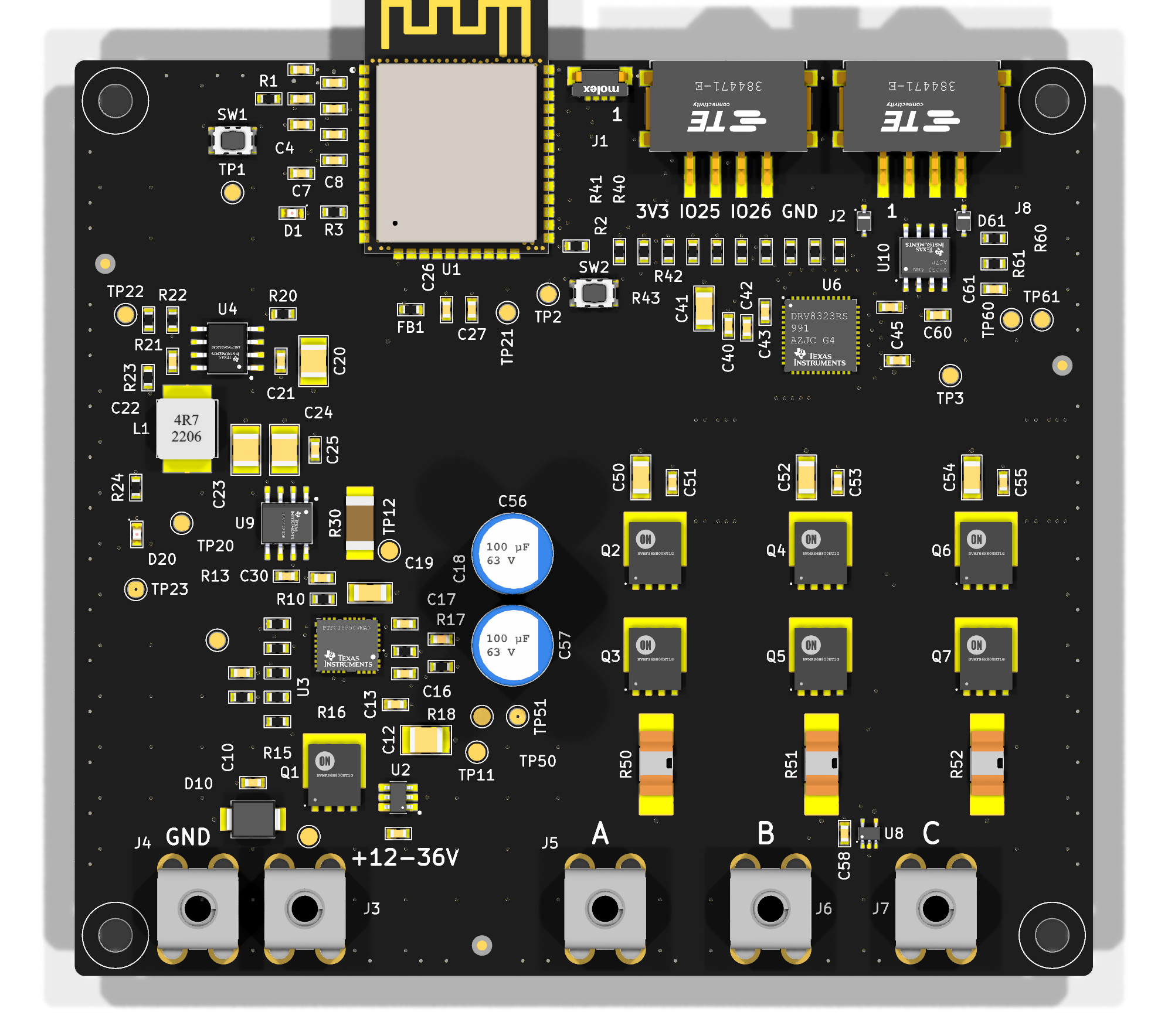
Main components on the R7
R7 bill of materials (BOM)
109 components, 52 distinct parts.
| Qty | Part | Footprint | Refs |
|---|---|---|---|
| 1 | ESP32-WROOM-32E Espressif Systems | ESP32-WROOM-32E | U1 |
| 1 | LM74700QDBVRQ1 Texas Instruments | SOT-23-6_DBV | U2 |
| 1 | PTPS16890VMAR Texas Instruments | 23-LQFN-CLIP_(VMA) | U3 |
| 1 | LMR38020FSDDAR Texas Instruments | 8-SOICPower | U4 |
| 1 | DRV8323RSRGZT Texas Instruments | 48-VQFN | U6 |
| 1 | TMP235A4DCKR Texas Instruments | SC-70-5 | U8 |
| 1 | INA240A1DR Texas Instruments | 8-SOIC | U9 |
| 1 | SN65HVD230DR Texas Instruments | 8-SOIC | U10 |
| 7 | NTMFS006N08MC onsemi | 8-PowerTDFN(5x6mm) | Q1, Q2, Q3, Q4, Q5, Q6, Q7 |
| 1 | UART Molex | 2147210040 | J1 |
| 1 | EXPANSION TE Connectivity Erni | 384471-E | J2 |
| 1 | VIN+ Keystone Electronics | 7770 | J3 |
| 1 | GND Keystone Electronics | 7770 | J4 |
| 3 | PHASE Keystone Electronics | 7770 | J5, J6, J7 |
| 1 | CAN TE Connectivity Erni | 384471-E | J8 |
| 1 | RESET E-Switch | TL6330AF200Q | SW1 |
| 1 | BOOT E-Switch | TL6330AF200Q | SW2 |
| 2 | Green Würth Elektronik | 0603_Medium | D1, D20 |
| 1 | SMBJ36CA-13-F Diodes Incorporated | DO-214AA | D10 |
| 2 | CDSOD323-T24SC Diodes Incorporated | SOD-323 | D60, D61 |
Show 32 more
| Qty | Part | Footprint | Refs |
|---|---|---|---|
| 1 | BLM18EG221SN1D Murata Electronics | 0603_Medium | FB1 |
| 1 | 4.7µH Eaton - Electronics Division | 6x5_7mm | L1 |
| 1 | 22 µF Samsung Electro-Mechanics | 0603_Medium | C1 |
| 10 | 100 nF YAGEO | 0603_Medium | C2, C14, C18, C22, C25, C27, C30, C45 +2 |
| 2 | 1 µF Murata Electronics | 0603_Medium | C3, C44 |
| 6 | 220 pF Samsung Electro-Mechanics | 0603_Medium | C4, C5, C6, C7, C8, C15 |
| 7 | 100 nF 100V Samsung Electro-Mechanics | 0603_Medium | C10, C13, C21, C40, C51, C53, C55 |
| 1 | 100 nF 16V YAGEO | 0603_Medium | C11 |
| 2 | 4.7 µF 100V Samsung Electro-Mechanics | 1210_Medium | C12, C20 |
| 1 | 22 pF Samsung Electro-Mechanics | 0603_Medium | C16 |
| 1 | 1 nF Murata Electronics | 0603_Medium | C17 |
| 5 | 10 µF 100V TDK Corporation | 1206_Medium | C19, C41, C50, C52, C54 |
| 2 | 47 µF Taiyo Yuden | 1210_Medium | C23, C24 |
| 1 | 10 µF Samsung Electro-Mechanics | 0603_Medium | C26 |
| 1 | 1 µF 100V Murata Electronics | 0603_Medium | C42 |
| 1 | 47 nF 100V Würth Elektronik | 0603_Medium | C43 |
| 2 | 100 µF 63V Cornell Dubilier Knowles | 8.00x13.50mm | C56, C57 |
| 1 | 4.7 nF Murata Electronics | 0603_Medium | C61 |
| 16 | 10 kOhm YAGEO | 0603_Medium | R1, R2, R13, R14, R15, R16, R40, R41 +8 |
| 2 | 1 kOhm Stackpole Electronics Inc | 0603_Medium | R3, R24 |
| 1 | 120 Ohm Stackpole Electronics Inc | 0603_Medium | R10 |
| 1 | 866 kOhm Stackpole Electronics Inc | 0603_Medium | R11 |
| 1 | 118 kOhm Stackpole Electronics Inc | 0603_Medium | R12 |
| 1 | 3.65 kOhm Stackpole Electronics Inc | 0603_Medium | R17 |
| 1 | 1.33 kOhm Stackpole Electronics Inc | 0603_Medium | R18 |
| 1 | 54.9 kOhm Stackpole Electronics Inc | 0603_Medium | R20 |
| 1 | 110 kOhm Stackpole Electronics Inc | 0603_Medium | R21 |
| 1 | 47 kOhm Stackpole Electronics Inc | 0603_Medium | R22 |
| 1 | 100 kOhm Stackpole Electronics Inc | 0603_Medium | R23 |
| 1 | 5 mOhm Isabellenhuette USA | 2010 | R30 |
| 3 | 2 mOhm Littelfuse Inc. | 2512 | R50, R51, R52 |
| 2 | 56 Ohm Stackpole Electronics Inc | 0603_Medium | R60, R61 |
R7 design files
The KiCad project lives in the odtu/PCBDesignWClaude repository on GitHub; these links point at the commit this page was built from.
R7: common questions
What microcontroller does the R7 use?
The R7 is built around the ESP32-WROOM-32E, from the ESP32 family.
How big is the R7 PCB?
The R7 measures 100 × 90 mm, has 4 copper layers and is 1.6 mm thick.
How many components are on the R7?
109 components, from 52 distinct parts. The full bill of materials is listed on this page.
Where can I download the R7 design files?
From the odtu/PCBDesignWClaude repository on GitHub, which has the KiCad layout; the links under Design files point to each one.
Can I use the R7 design in my own project?
Yes, under the terms of its CERN-OHL-S-2.0 license, which odtu chose for the repository.
Can I test firmware for the R7 without the hardware?
Yes. HardLabs builds a simulation of the board from its netlist and BOM, so you can run and debug ESP32 firmware against it before you order a PCB.
More boards in PCBDesignWClaude
Similar boards
 ESP32
ESP32Open Book Abridged Edition
joeycastillo
85 × 115 mm65 parts2LCC-BY-SA-4.08.1k ESP32
ESP32Badge
atopile
56.3 × 39 mm239 parts4LMIT4.0k ESP32
ESP32Esp32 minimal
36.2 × 26.8 mm20 parts2LMIT4.0k ESP32
ESP32Racer
StuckAtPrototype
36 × 50.2 mm70 parts4LApache-2.03.8k ESP32
ESP32Controller
29 × 74 mm58 parts4LApache-2.03.8k ESP32
ESP32Bitaxe
skot
56.5 × 99.8 mm86 parts4LCERN-OHL-S-2.01.4k