
Openrz67-trigger

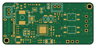
About the Openrz67-trigger PCB
Openrz67-trigger is an open source ESP32 PCB design by openrz67, published on GitHub under the MIT license. It is a 2-layer board measuring 48 × 22 mm, with 59 components from 34 distinct parts.
Its main chip is the ESP32-C3FH4, from the ESP32 family. Other key parts include the TPS63031DSKR, BQ25185DLHR, C157925, TLP172AM and C88374. By type, the board carries 22 capacitors, 17 resistors, 6 ICs, 3 switches, 3 inductors and 2 crystals.
It belongs with the iot & wireless and power & battery designs in this gallery.
From the project
Bluetooth remote release for the Mamiya RZ67: ESP32-C3 firmware, KiCad PCB and enclosure. Shutter, bulb and countdown from your phone.
KiCad 10 project for the OpenRZ67 trigger board (48 × 22 mm, 2 layers, ESP32-C3, two TLP172AM PhotoMOS relays, BQ25185 charger + TPS63031 buck-boost). This is now the source; the EasyEDA Pro project it was ported from is archived in ../archive/easyeda/ (v2 .epro and v3 .epro2); each fabricated revision's upload package is in ../archive/-rev/ (rev 1 2025-09-23, rev 2 2026-09-07).
Main components on the Openrz67-trigger
Openrz67-trigger bill of materials (BOM)
59 components, 34 distinct parts — part numbers from the project's BOM.
| Qty | Part | Footprint | Refs |
|---|---|---|---|
| 1 | ESP32-C3FH4 ESPRESSIF(乐鑫) | QFN-32_L5.0-W5.0-P0.50-BL-EP3.7 | U1 |
| 1 | TPS63031DSKR Texas Instruments | VSON-10_L2.5-W2.5-P0.50-EP1.2x2.0 | U2 |
| 1 | BQ25185DLHR Texas Instruments | WSON-10_L2.2-W2.0-P0.40-EP0.9x1.5 | U3 |
| 1 | C157925 S4B-XH-A(LF)(SN) JST | CONN-TH_S4B-XH-A-LF-SN | U4 |
| 2 | TLP172AM TOSHIBA(东芝) | SMD-4_L4.6-W3.7-P2.54-LS7.0-BR | U5, U6 |
| 1 | C88374 U.FL-R-SMT-1(80) HRS(广濑) | RF-SMD_FRF05002-JSS103M | A1 |
| 1 | AO3401A Alpha & Omega Semicon | SOT-23 | Q3 |
| 1 | T201640MFBDE2X 40MHz YJX(雅晶鑫) | CRYSTAL-SMD_4P-L2.0-W1.6-BL-2 | X1 |
| 1 | XKXGI-SUA-32.768K 32.768kHz YXC(扬兴晶振) | CRYSTAL-SMD_L3.2-W1.5-1 | X2 |
| 1 | C131337 B2B-PH-K-S(LF)(SN) JST | CONN-TH_B2B-PH-K-S | BAT1 |
| 2 | B3U-1000P OMRON(欧姆龙) | KEY-SMD_B3U-1000PM | S1, S2 |
| 1 | C131337 B2B-PH-K-S(LF)(SN) JST | CONN-TH_B2B-PH-K-S | S3 |
| 1 | C2765186 TYPE-C 16PIN 2MD(073) SHOU HAN(首韩) | USB-C-SMD_TYPE-C-6PIN-2MD-073 | USB1 |
| 1 | KT-0603R KENTO | LED0603-RD | D3 |
| 1 | XL-1608UBC-04 XINGLIGHT(成兴光) | LED0603-RD_BLUE | D4 |
| 1 | LQG15HS3N9S02D 3.9nH muRata(村田) | L0402 | L1 |
| 1 | BLM15AG601SN1D muRata(村田) | L0402 | L2 |
| 1 | SPM6530T-2R2M 2.2uH TDK | IND-SMD_L7.1-W6.5-P5.60 | L3 |
| 2 | CC0402CRNPO9BN1R0 1pF YAGEO(国巨) | C0402 | C1, C2 |
| 7 | GRM155R71H104KE14D 100nF muRata(村田) | C0402 | C3, C4, C5, C6, C7, C25, C32 |
Show 14 more
| Qty | Part | Footprint | Refs |
|---|---|---|---|
| 2 | GJM1555C1H150FB01D 15pF muRata(村田) | C0402 | C8, C9 |
| 3 | CL10A105KB8NNNC 1uF Samsung Electro-Mechanics | C0603 | C14, C26, C29 |
| 6 | CL10A106MA8NRNC 10uF SAMSUNG(三星) | C0603 | C15, C20, C21, C22, C23, C24 |
| 2 | GRM1555C1H180FA01D 18pF muRata(村田) | C0402 | C30, C31 |
| 2 | 0402WGF220JTCE 22Ω UNI-ROYAL(厚声) | R0402 | R4, R5 |
| 4 | 0402WGF1002TCE 10kΩ UNI-ROYAL(厚声) | R0402 | R6, R7, R8, R23 |
| 2 | 0402WGF5101TCE 5.1kΩ UNI-ROYAL(厚声) | R0402 | R9, R10 |
| 1 | 0402WGF2701TCE 2.7kΩ UNI-ROYAL(厚声) | R0402 | R11 |
| 1 | 0402WGF1802TCE 18kΩ UNI-ROYAL(厚声) | R0402 | R13 |
| 1 | NCP18XH103F03RB muRata(村田) | R0603 | R16 |
| 1 | FRC0402F3001TS 3kΩ FOJAN | R0402 | R18 |
| 1 | 0402WGF1001TCE 1kΩ UNI-ROYAL(厚声) | R0402 | R20 |
| 2 | 0402WGF1500TCE 150Ω UNI-ROYAL(厚声) | R0402 | R21, R22 |
| 2 | 0402WGF1004TCE 1MΩ UNI-ROYAL(厚声) | R0402 | R24, R25 |
Openrz67-trigger design files
The KiCad project lives in the openrz67/openrz67-trigger repository on GitHub; these links point at the commit this page was built from.
Openrz67-trigger: common questions
What microcontroller does the Openrz67-trigger use?
The Openrz67-trigger is built around the ESP32-C3FH4, from the ESP32 family.
How big is the Openrz67-trigger PCB?
The Openrz67-trigger measures 48 × 22 mm, has 2 copper layers and is 1.6 mm thick.
How many components are on the Openrz67-trigger?
59 components, from 34 distinct parts, with part numbers taken from the project's own BOM. The full bill of materials is listed on this page.
Where can I download the Openrz67-trigger design files?
From the openrz67/openrz67-trigger repository on GitHub, which has the KiCad layout, the schematic and the BOM; the links under Design files point to each one.
Can I use the Openrz67-trigger design in my own project?
Yes, under the terms of its MIT license, which openrz67 chose for the repository.
Can I test firmware for the Openrz67-trigger without the hardware?
Yes. HardLabs builds a simulation of the board from its netlist and BOM, so you can run and debug ESP32 firmware against it before you order a PCB.
Similar boards
 ESP32
ESP32Open Book Abridged Edition
joeycastillo
85 × 115 mm65 parts2LCC-BY-SA-4.08.1k ESP32
ESP32Badge
atopile
56.3 × 39 mm239 parts4LMIT4.0k ESP32
ESP32Esp32 minimal
36.2 × 26.8 mm20 parts2LMIT4.0k ESP32
ESP32Racer
StuckAtPrototype
36 × 50.2 mm70 parts4LApache-2.03.8k ESP32
ESP32Controller
29 × 74 mm58 parts4LApache-2.03.8k ESP32
ESP32Bitaxe
skot
56.5 × 99.8 mm86 parts4LCERN-OHL-S-2.01.4k