
ESP-Mini-PF-base circuit

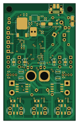
About the ESP-Mini-PF-base circuit PCB
ESP-Mini-PF-base circuit is an open source ESP32 PCB design by p3pperPi, published on GitHub. It is a 2-layer board measuring 39 × 63 mm, with 87 components from 52 distinct parts.
Its main chip is the ESP32-WROOM-32, from the ESP32 family. Other key parts include the CN39033A, CH340X, UZ1085L-33-TN3-R, TXB0104RUT and CP3119MDTR. By type, the board carries 26 resistors, 17 jumpers, 12 connectors, 10 ICs, 10 capacitors and 8 diodes.
From the project
ESP32-S3-wroom を使用した、DCモータでライントレースをするための基板です
また、JP17をショートすることで、モータ電源にUSB 5Vを使用することが可能です。 ただし、JP17をショートした状態で電源コネクタに5V以外の電圧をかけると、接続した機器が破損します。 JP17をショートさせた際は、絶対に電源コネクタから給電は行わないでください。 なお、JP17にはダイオードを入れて逆流防止を行うことも可能です。その際は、SBM245Lを使用してください。
入力電源は、DCDCコンバータモジュールCN39033Aを使用して5Vまで電圧を下げられます。
上で生成された5Vから、UZ1085L-22-TN3-Rを使用し、マイコンへの電源供給を行います。 | 項目 | 値 | 単位 | | ---------------- | --- | ---- | | 最大定格入力電圧 | 18 | V | | 最大電流(Typ.) | 4 | A |
Main components on the ESP-Mini-PF-base circuit
ESP-Mini-PF-base circuit bill of materials (BOM)
87 components, 52 distinct parts — part numbers from the project's BOM.
| Qty | Part | Footprint | Refs |
|---|---|---|---|
| 1 | CN39033A | DCDC_Conv_CN39033A | U1 |
| 1 | CH340X | MSOP-10_3x3mm_P0.5mm | U2 |
| 1 | UZ1085L-33-TN3-R | TO-252-2 | U3 |
| 1 | TXB0104RUT | Texas_R-PUQFN-N12 | U4 |
| 2 | CP3119MDTR | SOP-8_3.9x4.9mm_P1.27mm | U5, U6 |
| 1 | ESP32-WROOM-32 | ESP32-WROOM-32_39P-TH | U7 |
| 3 | ITR8307-S17-TR8 | Everlight_ITR1201SR10AR | U8, U9, U10 |
| 3 | U4_ALT2 | LED_D3.0mm | Q1, Q2, Q3 |
| 1 | VIN_1 Vin_1 | JST_PH_B2B-PH-K_1x02_P2.00mm_Vertical | J1 |
| 1 | x Power_SW | JST_PH_B2B-PH-K_1x02_P2.00mm_Vertical | J2 |
| 1 | x Vin_XT | AMASS_XT60-M_1x02_P7.20mm_Vertical | J3 |
| 1 | C428495 USB_B_Micro | USB_Micro-B_Amphenol_10103594-0001LF_Horizontal | J4 |
| 1 | x Encorder_L | JST_ZH_B4B-ZH-A_1x04_P1.50mm_Vertical | J5 |
| 1 | x Encorder_R | JST_ZH_B4B-ZH-A_1x04_P1.50mm_Vertical | J6 |
| 1 | x MOTOR_L | TerminalBlock_bornier-2_P5.08mm | J7 |
| 1 | x MOTOR_R | TerminalBlock_bornier-2_P5.08mm | J8 |
| 1 | IO4_GPIO0 | PinHeader_1x03_P2.54mm_Vertical | J9 |
| 1 | IO27_GPIO1 | PinHeader_1x03_P2.54mm_Vertical | J10 |
| 1 | IO32_GPIO2 | PinHeader_1x03_P2.54mm_Vertical | J11 |
| 1 | x IO5_GPIO3(PU) | PinHeader_1x03_P2.54mm_Vertical | J12 |
Show 32 more
| Qty | Part | Footprint | Refs |
|---|---|---|---|
| 1 | BSMD0603-050-6V BSMD0603-050-6Vn | Fuse_0603_1608Metric | F1 |
| 1 | x Power_SW_DIisable | SolderJumper-2_P1.3mm_Open_RoundedPad1.0x1.5mm | JP1 |
| 1 | L1_PU | SolderJumper-2_P1.3mm_Open_RoundedPad1.0x1.5mm | JP2 |
| 1 | L2_PU | SolderJumper-2_P1.3mm_Open_RoundedPad1.0x1.5mm | JP3 |
| 1 | R1_PU | SolderJumper-2_P1.3mm_Open_RoundedPad1.0x1.5mm | JP4 |
| 1 | R2_PU | SolderJumper-2_P1.3mm_Open_RoundedPad1.0x1.5mm | JP5 |
| 1 | VS_SEL0 Vs_SEL0 | SolderJumper-3_P1.3mm_Open_RoundedPad1.0x1.5mm | JP6 |
| 1 | VS_SEL1 Vs_SEL1 | SolderJumper-3_P1.3mm_Open_RoundedPad1.0x1.5mm | JP7 |
| 1 | VS_SEL2 Vs_SEL2 | SolderJumper-3_P1.3mm_Open_RoundedPad1.0x1.5mm | JP8 |
| 1 | VS_SEL3 Vs_SEL3 | SolderJumper-3_P1.3mm_Open_RoundedPad1.0x1.5mm | JP9 |
| 3 | LED_SEL1 | SolderJumper-3_P1.3mm_Open_RoundedPad1.0x1.5mm | JP10, JP12, JP14 |
| 3 | PT_SEL1 | SolderJumper-3_P1.3mm_Open_RoundedPad1.0x1.5mm | JP11, JP13, JP15 |
| 1 | x Reset | SolderJumper-2_TVAF06-A020B-R_COMPATIBLE | JP16 |
| 1 | x USB_Vs | D_DO-41_SOD81_P7.62mm_Horizontal | JP17 |
| 1 | CDBA240LL-HF | D_SMA | D1 |
| 1 | x LED_POWER | LED_D3.0mm | D2 |
| 1 | x LED_R | LED_D3.0mm | D3 |
| 1 | x LED_Y | LED_D3.0mm | D4 |
| 1 | x LED_G | LED_D3.0mm | D5 |
| 3 | U4_ALT1 | LED_D3.0mm | D6, D7, D8 |
| 2 | 22U 22u | CP_Radial_D5.0mm_P2.00mm | C1, C2 |
| 4 | 0.1U 0.1u | C_0402_1005Metric | C3, C4, C8, C10 |
| 1 | 10U 10u | C_0402_1005Metric | C5 |
| 1 | 20P 20p | C_0402_1005Metric | C6 |
| 2 | 470U 470u | CP_Radial_D8.0mm_P3.50mm | C7, C9 |
| 1 | 18K 18k | R_0402_1005Metric | R1 |
| 1 | 2k | R_0402_1005Metric | R2 |
| 2 | 22 | R_0402_1005Metric | R3, R4 |
| 1 | 4.7K 4.7k | R_0402_1005Metric | R5 |
| 13 | 1k | R_0402_1005Metric | R6, R8, R10, R11, R12, R13, R17, R18 +5 |
| 5 | 560 | R_0402_1005Metric | R7, R9, R14, R15, R16 |
| 3 | 50 | R_0805_2012Metric | R21, R23, R25 |
ESP-Mini-PF-base circuit design files
The KiCad project lives in the p3pperPi/ESP-Mini-PF-base-circuit repository on GitHub; these links point at the commit this page was built from.
ESP-Mini-PF-base circuit: common questions
What microcontroller does the ESP-Mini-PF-base circuit use?
The ESP-Mini-PF-base circuit is built around the ESP32-WROOM-32, from the ESP32 family.
How big is the ESP-Mini-PF-base circuit PCB?
The ESP-Mini-PF-base circuit measures 39 × 63 mm, has 2 copper layers and is 1.6 mm thick.
How many components are on the ESP-Mini-PF-base circuit?
87 components, from 52 distinct parts, with part numbers taken from the project's own BOM. The full bill of materials is listed on this page.
Where can I download the ESP-Mini-PF-base circuit design files?
From the p3pperPi/ESP-Mini-PF-base-circuit repository on GitHub, which has the KiCad layout, the schematic and the BOM; the links under Design files point to each one.
Can I use the ESP-Mini-PF-base circuit design in my own project?
The repository has no license, so all rights stay with p3pperPi. Use it as a reference, and ask the author before reusing the design.
Can I test firmware for the ESP-Mini-PF-base circuit without the hardware?
Yes. HardLabs builds a simulation of the board from its netlist and BOM, so you can run and debug ESP32 firmware against it before you order a PCB.
Similar boards
 ESP32
OSO-BOOK-B1
joeycastillo
85 × 115 mm65 parts2LCC-BY-SA-4.08.1k ESP32
Powertrain
byrantech
64 × 45.4 mm171 parts4LMIT4.3k ESP32
Esp32 minimal
atopile
36.2 × 26.8 mm20 parts2LMIT4.0k ESP32
Badge
56.3 × 39 mm239 parts4LMIT4.0k ESP32
Racer
StuckAtPrototype
36 × 50.2 mm70 parts4LApache-2.03.8k ESP32
Controller
29 × 74 mm58 parts4LApache-2.03.8k