
RoboCape

About the RoboCape PCB
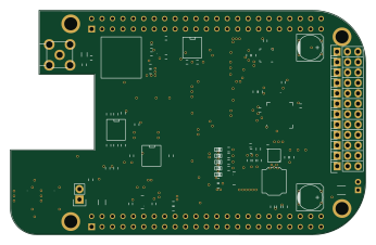
RoboCape is an open source PCB design by PREDICT-EPFL, published on GitHub. It is a board measuring 86.4 × 54.6 mm, with 113 components from 58 distinct parts.
Other key parts include the BEAGLEBONE, CAT24C256W, BQ32000, XBee_Header and PCA9685. By type, the board carries 40 resistors, 26 capacitors, 11 ICs, 6 diodes, 2 fuses and 2 inductors.
It belongs with the robotics & motion designs in this gallery.
From the project
This repository is dedicated to a Beaglebone cape extension developped at EPFL in the Automatic Control Laboratory. The idea of this platform is to allow the user to transform any mechanically actuated platform, for example a RC car or a quadcopter base, into a robotic vehicle th
This repository is dedicated to a Beaglebone cape extension developped at EPFL in the Automatic Control Laboratory. The idea of this platform is to allow the user to transform any mechanically actuated platform, for example a RC car or a quadcopter base, into a robotic vehicle that can be controlled by a remote server.
The repository contains all the design files of the Beaglebone cape extension. Schematic PCB layout Production files Documentation files (useful documents and datasheets)
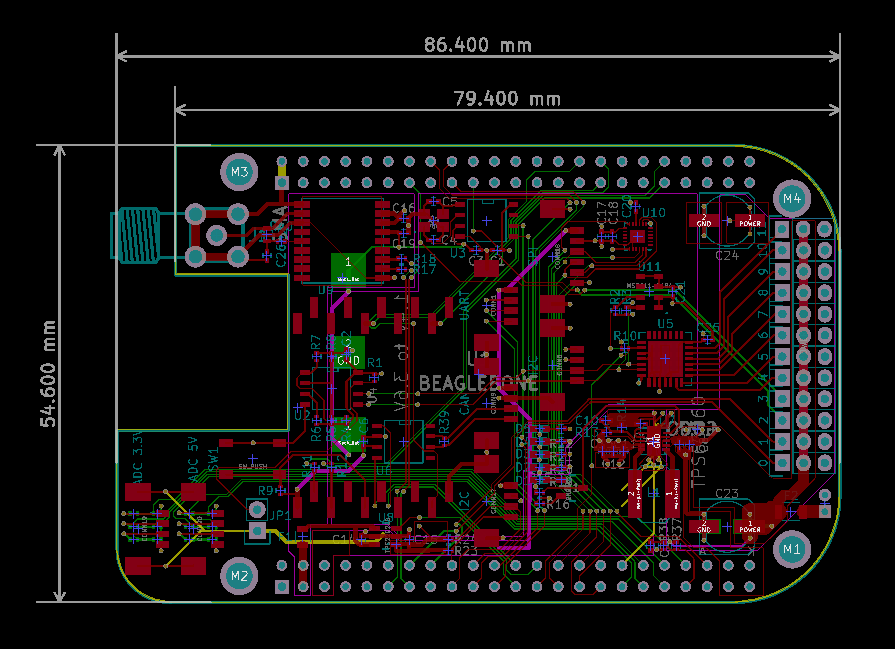
Main components on the RoboCape
RoboCape bill of materials (BOM)
113 components, 58 distinct parts.
| Qty | Part | Footprint | Refs |
|---|---|---|---|
| 1 | BEAGLEBONE | BEAGLEBONE | U1 |
| 1 | CAT24C256W | SOIC-8-N | U2 |
| 1 | BQ32000 | SOIC-8-N | U3 |
| 1 | XBee_Header | Xbee_Header_SMD | U4 |
| 1 | PCA9685 | QFN-28-1EP_6x6mm_Pitch0.65mm | U5 |
| 1 | SN65HVD232D | SOIC-8-N | U6 |
| 1 | TPS63060 | SON-10 | U7 |
| 1 | TPS22929D | _TSOT23-6 | U8 |
| 1 | MAX-M8 | MAX-M8 | U9 |
| 1 | MPU-9250 | QFN-24-1EP_3x3mm_Pitch0.4mm | U10 |
| 1 | MS5611-01BA | _MS5611-01BA | U11 |
| 1 | 2N7002 | _SOT23-3 | Q1 |
| 1 | 32768Hz | _TSX-3225-SMD-XTAL | X1 |
| 1 | SMA | SMA-CONN | J1 |
| 12 | SERVO | Pin_Header_Straight_1x03 | 0, 1, 2, 3, 4, 5, 6, 7 +4 |
| 1 | 1.4V to 3.6V | BK-885 | BT1 |
| 1 | UART | _Molex-PicoBlade-SMD-4 | CONN1 |
| 2 | I2C | _Molex-PicoBlade-SMD-4 | CONN5, CONN17 |
| 1 | CAN | _Molex-PicoBlade-SMD-4 | CONN9 |
| 1 | PWR | _Pin2mm_2 | CONN16 |
Show 38 more
| Qty | Part | Footprint | Refs |
|---|---|---|---|
| 1 | SPI | _Molex-PicoBlade-SMD-6 | CONN18 |
| 1 | ADC 3.3V | _Molex-PicoBlade-SMD-4 | CONN19 |
| 1 | ADC 5V | _Molex-PicoBlade-SMD-4 | CONN20 |
| 1 | 500mA | R_0805 | F1 |
| 1 | 10A | R_1206 | F2 |
| 1 | Jumper_NC_Small | Pin_Header_Straight_1x02 | JP1 |
| 1 | SW_PUSH | _PTS525SK15-SMT-Pushbutton | SW1 |
| 1 | YELLOW | LED-0603 | D1 |
| 1 | WHITE | LED-0603 | D2 |
| 1 | GREEN | LED-0603 | D3 |
| 1 | BLUE | LED-0603 | D4 |
| 1 | RED | LED-0603 | D5 |
| 1 | ZENER 12V | Diode-SMA_Standard | D6 |
| 1 | 1uH | Laird_TYS6045 | L1 |
| 1 | L | R_0603 | L2 |
| 3 | 1u | C_0402 | C1, C14, C15 |
| 8 | 100n | C_0402 | C2, C6, C9, C17, C20, C21, C22, C25 |
| 1 | 220n | C_0402 | C3 |
| 3 | 10p | C_0402 | C4, C5, C10 |
| 2 | 10u | C_0402 | C7, C8 |
| 3 | 22u | C_0402 | C11, C12, C13 |
| 2 | 0.1u | C_0402 | C16, C19 |
| 1 | 10n | C_0402 | C18 |
| 2 | 100u | c_elec_6.3x7.7 | C23, C24 |
| 1 | C | C_0402 | C26 |
| 2 | 10k | R_0402 | R1, R10 |
| 8 | 4.7k | R_0402 | R2, R3, R4, R5, R6, R23, R24, R37 |
| 2 | 0 | R_0402 | R7, R8 |
| 1 | 50k | R_0402 | R9 |
| 4 | 330 | R_0402 | R11, R12, R17, R18 |
| 2 | 1M | R_0402 | R13, R15 |
| 1 | 111k | R_0402 | R14 |
| 5 | 1k | R_0402 | R16, R19, R20, R21, R22 |
| 3 | 680 | R_0402 | R25, R27, R29 |
| 7 | 820 | R_0402 | R26, R28, R30, R32, R34, R36, R38 |
| 3 | 1.47k | R_0402 | R31, R33, R35 |
| 1 | 120 | R_0402 | R39 |
| 1 | 10 | R_0402 | R40 |
RoboCape design files
The KiCad project lives in the PREDICT-EPFL/RoboCape repository on GitHub; these links point at the commit this page was built from.
- Layoutrobocape.kicad_pcb
RoboCape: common questions
How big is the RoboCape PCB?
The RoboCape measures 86.4 × 54.6 mm and is 1.6 mm thick.
How many components are on the RoboCape?
113 components, from 58 distinct parts. The full bill of materials is listed on this page.
Where can I download the RoboCape design files?
From the PREDICT-EPFL/RoboCape repository on GitHub, which has the KiCad layout; the links under Design files point to each one.
Can I use the RoboCape design in my own project?
The repository has no license, so all rights stay with PREDICT-EPFL. Use it as a reference, and ask the author before reusing the design.
Similar boards

Stack chan
stack-chan
50 × 50 mm33 parts2LApache-2.01.7k
Cube batteryboard
willem-pennings
95 × 95 mm4 parts2LGPL-3.01.1k
Mesabob
rene-dev
87.5 × 50 mm44 parts2LGPL-3.0979
Bob
100 × 100 mm140 parts2LGPL-3.0979
Triple adapter
57 × 75 mm26 parts2LGPL-3.0979
Trollerv2
100 × 75 mm33 parts4LGPL-3.0979