
FC Board v3

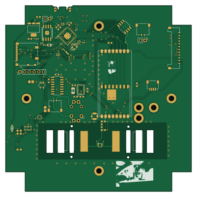
About the FC Board v3
FC Board v3 is an open source RP2040/RP2350 PCB design by proveskit, published on GitHub under the CERN-OHL-W-2.0 license. It is a 4-layer board measuring 100 × 100 mm, with 73 components from 48 distinct parts.
Its main chip is the RP2040_QFN56, from the RP2040/RP2350 family. Other key parts include the AZ1117CH-3.3TRG1, MAX706RESA, W25Q128JV, RFM98PW and RFM9XBREAKOUT. By type, the board carries 23 capacitors, 17 resistors, 11 ICs, 9 connectors, 3 crystals and 3 diodes.
It belongs with the robotics & motion, rf & radio and sensors designs in this gallery, and the repository also holds 1 earlier revision of it.
From the project
The main flight computer board for the PROVES Kit.
For detailed documentation on the Flight Controller Board, check out the docs here.
V0 through V3 Flight Controller Boards were the cornerstone of the 2023 Release V1 PROVES Kit. With the 2024 V2 PROVES Kit we introduced the V4 Flight Controller board and changed the version scheme to have a, b, c, etc varients of a single version rather than ascending the version ladder in record time (we'd be on V9 now if we did that!). This change was primarily based on the idea that a revisions on a major version number would be similar enough to each other to not require completely different firmware to…
Main components on the FC Board v3
FC Board v3 bill of materials (BOM)
73 components, 48 distinct parts — part numbers from the project's BOM.
| Qty | Part | Footprint | Refs |
|---|---|---|---|
| 1 | RP2040_QFN56 | QFN56_7MM_REDUCEDEPAD | IC1 |
| 1 | AZ1117CH-3.3TRG1 | SOT230P700X180-4N | IC2 |
| 1 | MAX706RESA | SO-8_3.9x4.9mm_P1.27mm | U1 |
| 1 | W25Q128JV | SOIC-8_5.275x5.275mm_P1.27mm | U2 |
| 1 | RFM98PW | RFM95PW | U3 |
| 1 | RFM9XBREAKOUT RFM9xBreakout | HOPERF_RFM9XW_SMD | U4 |
| 1 | VL6180XV0NR/1 | VL6180 | U5 |
| 1 | LP5907-2.8V | SOT23-5 | U6 |
| 1 | 74AHC4050 | SOIC127P600X175-16N | U7 |
| 1 | BNO080 | BNO080 | U8 |
| 1 | DNI | SON127P600X500X90-9N | U20 |
| 1 | BSS138 | SOT363 | Q1 |
| 1 | C234179 microUSB | MOLEX_105164-0001 | X1 |
| 1 | 32.768 | XTAL3215 | X2 |
| 1 | 12MHZ | CRYSTAL_2.5X2 | Y1 |
| 1 | FC to EPS Connector | Molex_Pico-Lock_504050-1291_1x12-1MP_P1.50mm_Horizontal | J1 |
| 1 | CONN_ARM_JTAG_SWD_10 Conn_ARM_JTAG_SWD_10 | 2X05_1.27MM_BOX_POSTS | J2 |
| 1 | FC to EPS Connector | PinHeader_1x06_P2.54mm_Vertical | J3 |
| 1 | usb jumper | PinHeader_1x02_P2.54mm_Vertical | J5 |
| 1 | Battery Charge Bypass | PinHeader_1x02_P2.54mm_Vertical | J6 |
Show 28 more
| Qty | Part | Footprint | Refs |
|---|---|---|---|
| 1 | Battery Charge Bypass | MOLEX_504050-0291 | J7 |
| 1 | FC to EPS Connector | MOLEX_504050-0291 | J8 |
| 1 | C160404 SM04B-SRSS-TB(LF)(SN) | JST_SM04B-SRSS-TB(LF)(SN) | J10 |
| 1 | 104031-0811 | 1040310811 | J44 |
| 1 | UHF_Dipole_Antenna | UHF_Dipole_Antenna_Mount | AE1 |
| 2 | KMR2 | BTN_KMR2_4.6X2.8 | SW1, SW2 |
| 1 | TESTPOINTROUND1.5MMNO | TESTPOINT_ROUND_1.5MM_NO | TP1 |
| 1 | WS2812B_SK6805_1515 | SK6805_1515 | LED1 |
| 1 | NSR0320 | SOD-323F | D1 |
| 1 | C72041 RED | CHIPLED_0603_NOOUTLINE | D2 |
| 1 | 1N4148 | SOD-323 | D3 |
| 1 | DNI | R_0603_1608Metric | L1 |
| 2 | 22PF 22pF | C_0402_1005Metric | C1, C2 |
| 3 | 1UF 1uF | C_0603_1608Metric | C3, C6, C8 |
| 6 | 0.1UF 0.1uF | C_0402_1005Metric | C4, C5, C7, C9, C10, C11 |
| 2 | 10UF 10uF | C_0603_1608Metric | C12, C16 |
| 2 | DNI | C_0603_1608Metric_Pad1.08x0.95mm_HandSolder | C13, C14 |
| 2 | 10UF 10uF | 0805-NO | C15, C17 |
| 1 | 0.1UF 0.1uF | 0603-NO | C18 |
| 1 | 22UF 22uF | C_0603_1608Metric | C19 |
| 2 | 0.1UF 0.1uF | C_0603_1608Metric | C20, C21 |
| 2 | 22PF 22pF | C_0603_1608Metric | C22, C23 |
| 5 | 10K | R_0402_1005Metric | R1, R7, R10, R11, R12 |
| 4 | 10K 10k | R_0603_1608Metric | R2, R8, R16, R19 |
| 3 | 1K | R_0402_1005Metric | R3, R4, R9 |
| 2 | 22 | R_0402_1005Metric | R5, R6 |
| 2 | 10K | 0603-NO | R13, R15 |
| 1 | 10K | RESPACK_4X0603 | R14 |
FC Board v3 design files
The KiCad project lives in the proveskit/flight_controller_board repository on GitHub; these links point at the commit this page was built from.
FC Board v3: common questions
What microcontroller does the FC Board v3 use?
The FC Board v3 is built around the RP2040_QFN56, from the RP2040/RP2350 family.
How big is the FC Board v3?
The FC Board v3 measures 100 × 100 mm, has 4 copper layers and is 1.6062 mm thick.
How many components are on the FC Board v3?
73 components, from 48 distinct parts, with part numbers taken from the project's own BOM. The full bill of materials is listed on this page.
Where can I download the FC Board v3 design files?
From the proveskit/flight_controller_board repository on GitHub, which has the KiCad layout, the schematic and the BOM; the links under Design files point to each one.
Can I use the FC Board v3 design in my own project?
Yes, under the terms of its CERN-OHL-W-2.0 license, which proveskit chose for the repository.
Can I test firmware for the FC Board v3 without the hardware?
Yes. HardLabs builds a simulation of the board from its netlist and BOM, so you can run and debug RP2040/RP2350 firmware against it before you order a PCB.
More boards in flight_controller_board
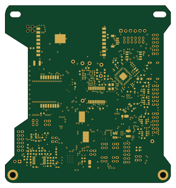 RP2040/RP2350
FC V5d Pro Rev1
88 × 94.5 mm255 parts4LCERN-OHL-W-2.06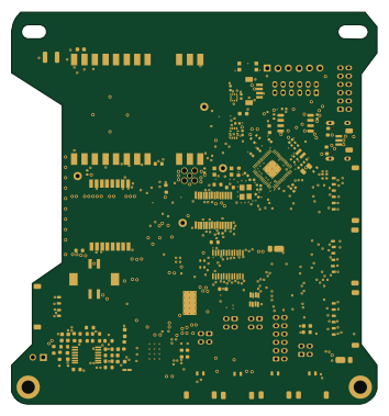 RP2040/RP2350
FC V5e Production Rev1
88 × 94.5 mm244 parts4LCERN-OHL-W-2.06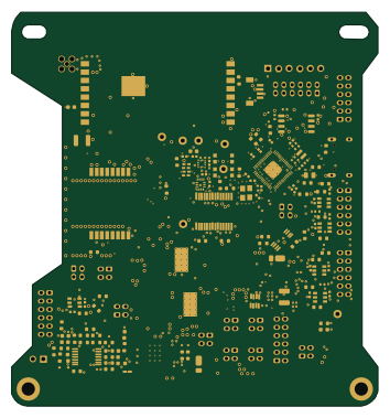 RP2040/RP2350
FC V5d Production Rev2
88 × 94.5 mm243 parts4LCERN-OHL-W-2.06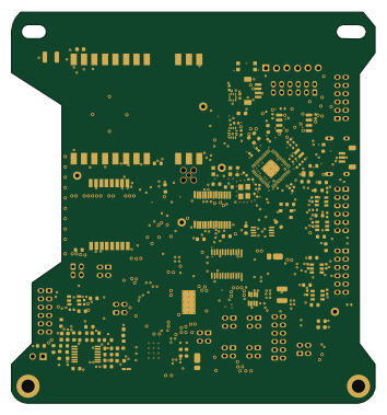 RP2040/RP2350
FC V5e
88 × 94.5 mm242 parts4LCERN-OHL-W-2.06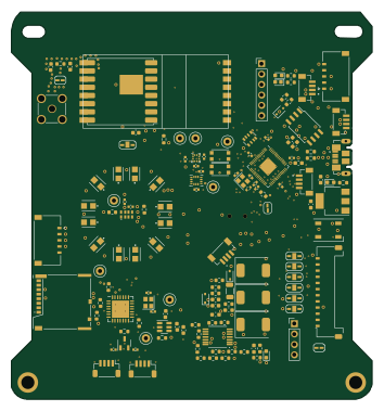 RP2040/RP2350
FC V4c Express
88 × 94.5 mm147 parts4LCERN-OHL-W-2.06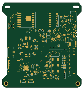 RP2040/RP2350
FC V4c InspireFly Special
88 × 94.5 mm144 parts4LCERN-OHL-W-2.06
Earlier revisions in the repo: FC_Board_v1
Similar boards
 RP2040/RP2350
Open Book Abridged Edition
joeycastillo
85 × 115 mm29 parts2LCC-BY-SA-4.08.1k RP2040/RP2350
Corne
foostan
277.2 × 107.5 mm164 parts2LCC-BY-4.07.7k RP2040/RP2350
Corne
277.2 × 107.5 mm164 parts2LCC-BY-4.07.7k RP2040/RP2350
LogicAnalyzer
gusmanb
57 × 55.2 mm6 parts2LGPL-3.05.0k RP2040/RP2350
Jitx design
55.5 × 65 mm26 parts4LGPL-3.05.0k RP2040/RP2350
Pro V2
kata0510
290.1 × 130 mm270 parts2LMIT2.3k