
RP2040 Motion Logger

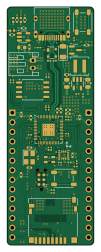
About the RP2040 Motion Logger PCB
RP2040 Motion Logger is an open source RP2040/RP2350 PCB design by rishikesh2715, published on GitHub under the MIT license. It is a 4-layer board measuring 22.9 × 63 mm, with 69 components from 45 distinct parts.
Its main chip is the RP2040, from the RP2040/RP2350 family. Other key parts include the TLV62569DBV, W25Q128JVS, MCP73831-2-OT and ICM-42688-P. By type, the board carries 27 capacitors, 19 resistors, 6 connectors, 6 diodes, 5 ICs and 2 switches.
It belongs with the power & battery, sensors and usb & debug tools designs in this gallery.
From the project
An RP2040 based microcontroller with an ICM-42688 IMU, 1S Battery Charger, SD Card Connector, RGB Led, and USB Type-C connector
I have slightly modified the board to include a bootloader button and made some aesthetic changes since having this board produced. Thus, the produced board slightly looks different. Everything else remains the same
You can order this board through PCBway for excellent board quality and fast shipping at a very affordable rate.
- Using PCBway as the manufacturer is recommended because the stackup for this board is based on their specifications. The differential impedance for the USB differential pair has been calculated based on PCBway’s stackup, ensuring that the board will perform as…
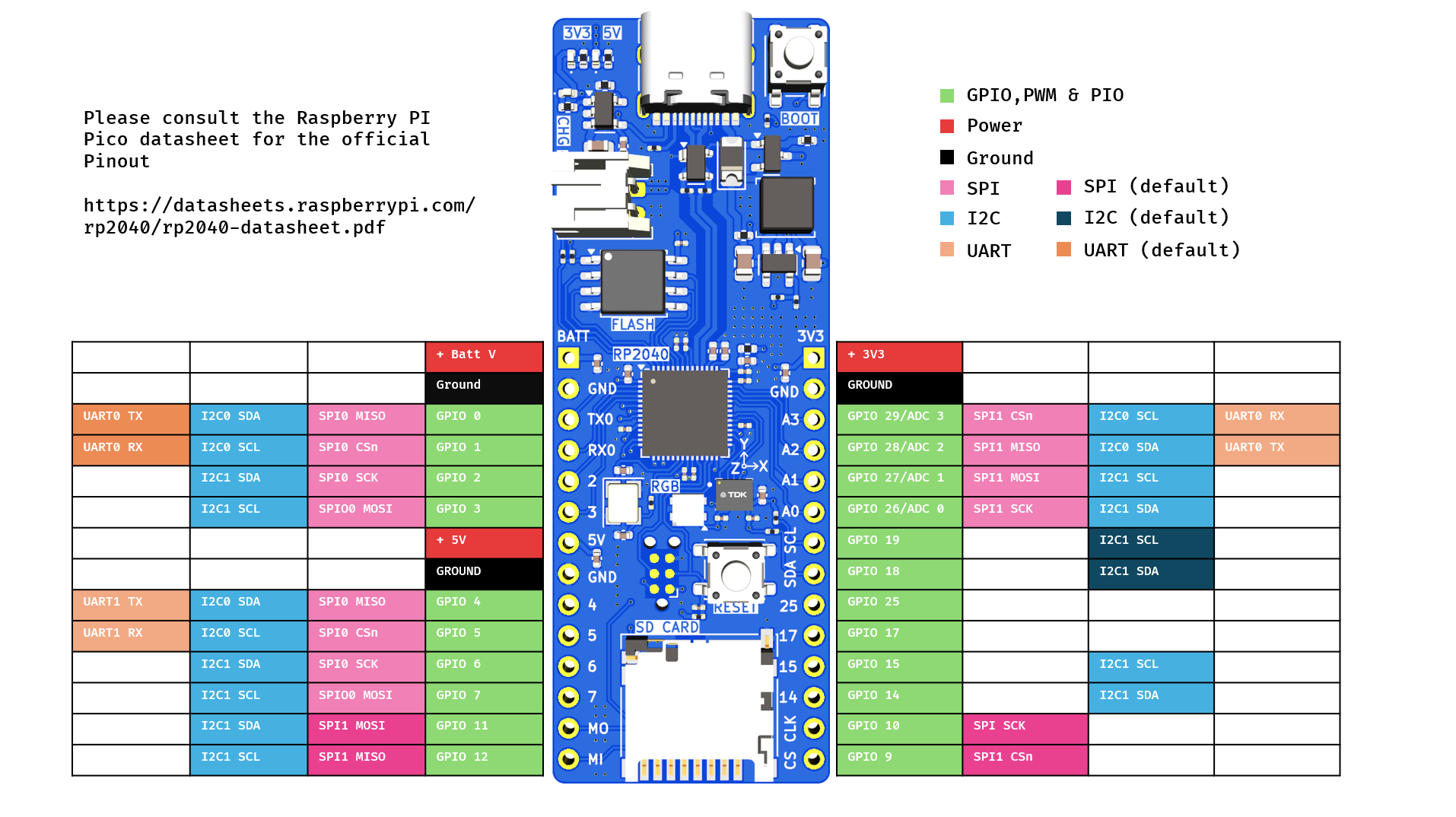
Main components on the RP2040 Motion Logger
RP2040 Motion Logger bill of materials (BOM)
69 components, 45 distinct parts.
| Qty | Part | Footprint | Refs |
|---|---|---|---|
| 1 | RP2040 | QFN-56-1EP_7x7mm_P0.4mm_EP3.2x3.2mm | U1 |
| 1 | TLV62569DBV | SOT-23-5 | U2 |
| 1 | W25Q128JVS | SOIC-8_5.23x5.23mm_P1.27mm | U3 |
| 1 | MCP73831-2-OT | SOT-23-5 | U4 |
| 1 | ICM-42688-P | PQFN50P300X250X97-14N | U6 |
| 1 | AO3401A | SOT-23 | Q1 |
| 1 | 12MHZ | Crystal_SMD_3225-4Pin_3.2x2.5mm | Y1 |
| 1 | Conn_01x02 | JST_PH_S2B-PH-K_1x02_P2.00mm_Horizontal | J1 |
| 2 | Conn_01x14 | PinHeader_1x14_P2.54mm_Vertical | J2, J5 |
| 1 | Micro_SD_Card_Det1 | microSD_HC_Hirose_DM3D-SF | J4 |
| 1 | Conn_01x02 | SolderJumper-2_P1.3mm_Open_TrianglePad1.0x1.5mm | J6 |
| 1 | USB_C_Plug_USB2.0 | USB_C_Receptacle_HRO_TYPE-C-31-M-12 | P1 |
| 1 | RESET | SW_SPST_PTS647_Sx38 | SW1 |
| 1 | BOOTLOADER | SW_SPST_PTS647_Sx38 | SW2 |
| 1 | PRTR5V0U2X | SOT-143 | D1 |
| 1 | Orange | LED_0402_1005Metric | D2 |
| 1 | SK6805 | LED_SK6805_PLCC4_2.4x2.7mm_P1.3mm | D4 |
| 1 | MBR0540 | D_1206_3216Metric | D5 |
| 2 | 3V3 | LED_0402_1005Metric | D6, D7 |
| 1 | 480R@100MHz | R_0402_1005Metric | FB1 |
Show 25 more
| Qty | Part | Footprint | Refs |
|---|---|---|---|
| 1 | 2u2 | L_Coilcraft_XAL4020-XXX | L1 |
| 2 | 10p | C_0402_1005Metric | C1, C2 |
| 6 | 1u | C_0402_1005Metric | C3, C9, C10, C15, C16, C27 |
| 10 | 100n | C_0201_0603Metric | C4, C5, C6, C7, C8, C11, C12, C14 +2 |
| 1 | 10u | C_0402_1005Metric | C13 |
| 1 | 4u7 | C_0402_1005Metric | C18 |
| 1 | 10u | C_0603_1608Metric | C19 |
| 1 | 0.1u | C_0201_0603Metric | C20 |
| 1 | 2u2 | C_0402_1005Metric | C21 |
| 1 | 10n | C_0201_0603Metric | C22 |
| 1 | 4u7 | C_0805_2012Metric | C24 |
| 1 | C_Small | C_0805_2012Metric | C25 |
| 1 | 100n | C_0805_2012Metric_Pad1.18x1.45mm_HandSolder | C26 |
| 2 | 1K | R_0201_0603Metric | R1, R16 |
| 2 | 5K1 | R_0201_0603Metric | R2, R3 |
| 2 | 27R | R_0201_0603Metric | R4, R5 |
| 1 | 4k7 | R_0201_0603Metric | R6 |
| 2 | 5K | R_0402_1005Metric | R7, R8 |
| 1 | DNF | R_0201_0603Metric | R10 |
| 2 | 10K | R_0402_1005Metric | R11, R12 |
| 1 | 442k | R_0201_0603Metric | R13 |
| 1 | 100k | R_0201_0603Metric | R14 |
| 1 | DNF | R_0805_2012Metric_Pad1.20x1.40mm_HandSolder | R15 |
| 2 | 5K1 | R_0402_1005Metric | R17, R20 |
| 2 | 10K | R_0201_0603Metric | R18, R19 |
RP2040 Motion Logger design files
The KiCad project lives in the rishikesh2715/RP2040_Motion_Logger repository on GitHub; these links point at the commit this page was built from.
- LayoutRP2040_Motion_Logger.kicad_pcb
- SchematicRP2040_Motion_Logger.kicad_sch
RP2040 Motion Logger: common questions
What microcontroller does the RP2040 Motion Logger use?
The RP2040 Motion Logger is built around the RP2040, from the RP2040/RP2350 family.
How big is the RP2040 Motion Logger PCB?
The RP2040 Motion Logger measures 22.9 × 63 mm, has 4 copper layers and is 1.596 mm thick.
How many components are on the RP2040 Motion Logger?
69 components, from 45 distinct parts. The full bill of materials is listed on this page.
Where can I download the RP2040 Motion Logger design files?
From the rishikesh2715/RP2040_Motion_Logger repository on GitHub, which has the KiCad layout and the schematic; the links under Design files point to each one.
Can I use the RP2040 Motion Logger design in my own project?
Yes, under the terms of its MIT license, which rishikesh2715 chose for the repository.
Can I test firmware for the RP2040 Motion Logger without the hardware?
Yes. HardLabs builds a simulation of the board from its netlist and BOM, so you can run and debug RP2040/RP2350 firmware against it before you order a PCB.
Similar boards
 RP2040/RP2350
Open Book Abridged Edition
joeycastillo
85 × 115 mm29 parts2LCC-BY-SA-4.08.1k RP2040/RP2350
Corne
foostan
277.2 × 107.5 mm164 parts2LCC-BY-4.07.7k RP2040/RP2350
Corne
277.2 × 107.5 mm164 parts2LCC-BY-4.07.7k RP2040/RP2350
LogicAnalyzer
gusmanb
57 × 55.2 mm6 parts2LGPL-3.05.0k RP2040/RP2350
Jitx design
55.5 × 65 mm26 parts4LGPL-3.05.0k RP2040/RP2350
Pro V2
kata0510
290.1 × 130 mm270 parts2LMIT2.3k