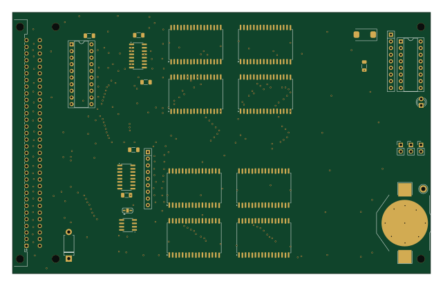
CPU09US4

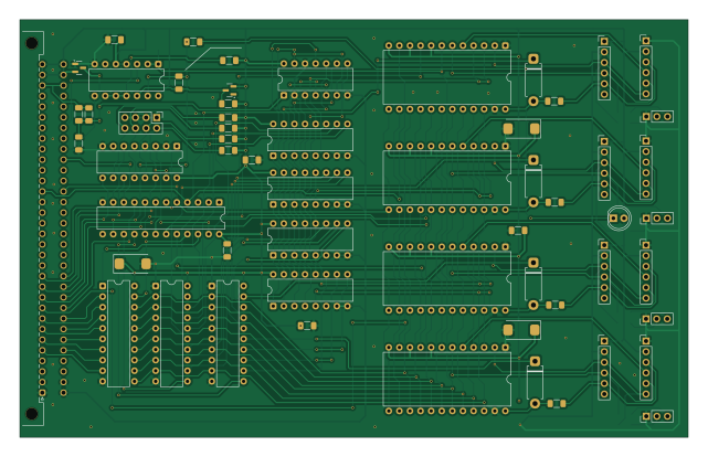
About the CPU09US4 PCB
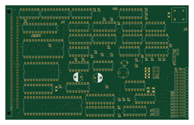
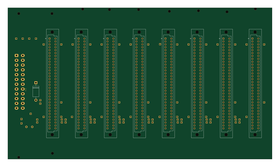
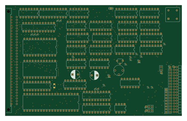
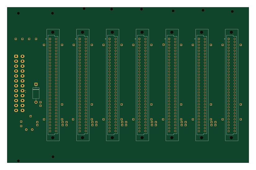
CPU09US4 is an open source PCB design by roberto314, published on GitHub. It is a 2-layer board measuring 160 × 100 mm, with 68 components from 26 distinct parts.
Other key parts include the 74HC245, 6850_DIL24, 74LS151, 74LS85 and 74LS125. By type, the board carries 22 resistors, 15 ICs, 10 capacitors, 7 diodes and 6 connectors.
From the project
kees 1948 Uniflex Remake
This is my recreation of the Uniflex Serial Board. It is a merge of the SR4 and the US4 Board with some SMD Components. It has two pinouts for external modules. One with a RS232 Converter and a female SUB-D9 connector, and one for a USB-Serial Converter with USB-C or micro-USB Connector. The modules can be found on ebay.
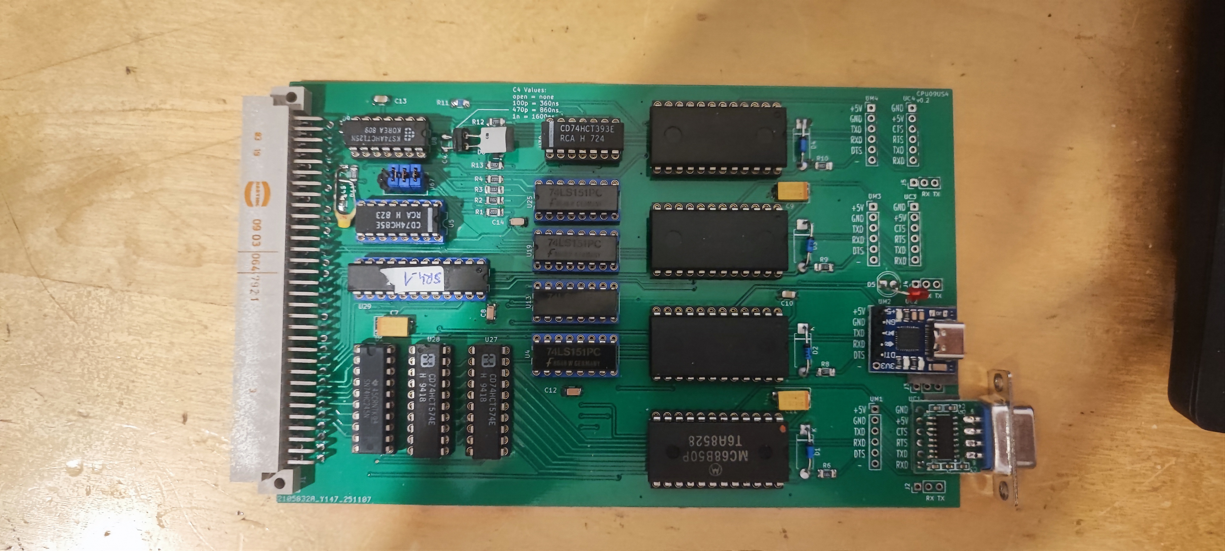
Main components on the CPU09US4
CPU09US4 bill of materials (BOM)
68 components, 26 distinct parts.
| Qty | Part | Footprint | Refs |
|---|---|---|---|
| 1 | 74HC245 | DIP-20_W7.62mm | U1 |
| 4 | 6850_DIL24 | DIP-24_W15.24mm | U2, U12, U18, U24 |
| 4 | 74LS151 | DIP-16_W7.62mm | U4, U13, U19, U25 |
| 1 | 74LS85 | DIP-16_W7.62mm | U5 |
| 1 | 74LS125 | DIP-14_W7.62mm | U8 |
| 2 | 74HC574 | DIP-20_W7.62mm | U27, U28 |
| 1 | GAL22V10 | DIP-24_W7.62mm | U29 |
| 1 | 74HC393 | DIP-14_W7.62mm | U30 |
| 1 | BUS | DIN41612_C_2x32_Male_Horizontal_THT | J1 |
| 4 | Conn_01x03 | PinHeader_1x03_P2.54mm_Vertical | J2, J3, J4, J5 |
| 1 | Conn_02x04_Odd_Even | PinHeader_2x04_P2.54mm_Vertical | J67 |
| 4 | Conn_01x06 | PinHeader_1x06_P2.54mm_Vertical | UC1, UC2, UC3, UC4 |
| 4 | USB | PinHeader_1x06_P2.54mm_Vertical | UM1, UM2, UM3, UM4 |
| 4 | BAT42 | D_DO-15_P10.16mm_Horizontal | D1, D2, D3, D4 |
| 1 | RED | LED_D5.0mm | D5 |
| 2 | BAS40-04 | SOT-23 | D6, D9 |
| 1 | C-M | C_1206_3216Metric_Pad1.33x1.80mm_HandSolder | C4 |
| 1 | 470p | C_1206_3216Metric_Pad1.33x1.80mm_HandSolder | C5 |
| 3 | 10u | CP_EIA-7343-31_Kemet-D_HandSolder | C7, C9, C11 |
| 5 | 100n | C_1206_3216Metric_Pad1.33x1.80mm_HandSolder | C8, C10, C12, C13, C14 |
Show 6 more
| Qty | Part | Footprint | Refs |
|---|---|---|---|
| 5 | 47k | R_1206_3216Metric_Pad1.30x1.75mm_HandSolder | R1, R2, R3, R4, R12 |
| 8 | 1k | R_1206_3216Metric_Pad1.30x1.75mm_HandSolder | R5, R16, R17, R18, R19, R20, R21, R22 |
| 6 | 10k | R_1206_3216Metric_Pad1.30x1.75mm_HandSolder | R6, R7, R8, R9, R10, R13 |
| 1 | 820E | R_1206_3216Metric_Pad1.30x1.75mm_HandSolder | R11 |
| 1 | 560E | R_1206_3216Metric_Pad1.30x1.75mm_HandSolder | R14 |
| 1 | 1M | R_1206_3216Metric_Pad1.30x1.75mm_HandSolder | R15 |
CPU09US4 design files
The KiCad project lives in the roberto314/kees1948_Boards repository on GitHub; these links point at the commit this page was built from.
CPU09US4: common questions
How big is the CPU09US4 PCB?
The CPU09US4 measures 160 × 100 mm, has 2 copper layers and is 1.6 mm thick.
How many components are on the CPU09US4?
68 components, from 26 distinct parts. The full bill of materials is listed on this page.
Where can I download the CPU09US4 design files?
From the roberto314/kees1948_Boards repository on GitHub, which has the KiCad layout and the schematic; the links under Design files point to each one.
Can I use the CPU09US4 design in my own project?
The repository has no license, so all rights stay with roberto314. Use it as a reference, and ask the author before reusing the design.