
Esp32InductanceMeterV2

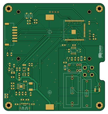
About the Esp32InductanceMeterV2 PCB
Esp32InductanceMeterV2 is an open source ESP32 PCB design by RobieElliz, published on GitHub under the MIT license. It is a 2-layer board measuring 94 × 99 mm, with 79 components from 51 distinct parts.
Its main chip is the ESP32-WROOM-32U, from the ESP32 family. Other key parts include the TPS631000DRLR, DW01A, TLV3202AIDR, 100nF MKP and IP2312. By type, the board carries 28 resistors, 17 capacitors, 8 ICs, 6 diodes, 4 connectors and 4 transformers.
It belongs with the displays & leds and power & battery designs in this gallery.
From the project
Portable ESP32 Inductance Meter: A low-cost, high-precision tool with dual 100nF/5µF refs, a TLV3202 comparator, fast USB-C (IP2312) charging, and a 2.4-inch OLED display for real-time readings.
A DIY ESP32-based inductance meter designed to bridge the gap in electronics testing. Developed at the Polytechnic University of the Philippines, this low-cost, high-precision tool is ideal for students, researchers, and hobbyists.
Accurate inductance measurement is crucial in electronics. Yet, professional meters are often expensive and inaccessible. This project provides an affordable alternative for educational and experimental applications.

Main components on the Esp32InductanceMeterV2
Esp32InductanceMeterV2 bill of materials (BOM)
79 components, 51 distinct parts.
| Qty | Part | Footprint | Refs |
|---|---|---|---|
| 1 | ESP32-WROOM-32U | ESP32-WROOM-32U | U1 |
| 1 | TPS631000DRLR | SOT-583-8_L2.1-W1.2-P0.50-LS1.6-BL | U2 |
| 1 | DW01A | SOT-23-6 | U3 |
| 1 | TLV3202AIDR | SOIC-8_L4.9-W3.9-P1.27-LS6.0-BL | U4 |
| 1 | 100nF MKP | CAP-TH_L26.0-W8.0-P22.50-D0.8 | U5 |
| 1 | IP2312 | SOP-8_L4.9-W3.9-P1.27-LS6.0-BL-EP | U6 |
| 1 | XH UART | CONN-SMD_S6B-XH-SM4-TB-LF-SN | U7 |
| 1 | ~ | 2.4 OLED I2C | U8 |
| 1 | FS8205A | SOT-23-6_L2.9-W1.6-P0.95-LS2.8-BR | Q1 |
| 1 | SS8050 | SOT-23 | Q2 |
| 1 | S Term | CONN-TH_2P-P2.54_MX128-2.54-GN01-02P-CU-Y-A | J1 |
| 3 | Touch | Touch_Pad_ESP | J2, J3, J4 |
| 1 | 18650 | BATTERY-SMD_18650-1S-L77.1-W20.7-1 | BT1 |
| 1 | G5V-1-DC3 | RELAY-TH_G5V-1 | K1 |
| 1 | BNC | BNC-TH_DOSIN-801-0051 | RF1 |
| 1 | BOOT | SW-SMD_L3.9-W3.0-P4.45 | SW1 |
| 1 | ENABLE | SW-SMD_L3.9-W3.0-P4.45 | SW2 |
| 1 | ON-OFF | SW-SMD_L3.9-W3.0-P4.45 | SW3 |
| 4 | Solderable Tie | Net-Tie 0805 Based | T1, T2, T3, T4 |
| 1 | TYPE-C 6P(073) | TYPE-C-SMD_TYPE-C-6P_5 | USB1 |
Show 31 more
| Qty | Part | Footprint | Refs |
|---|---|---|---|
| 1 | BAT54-7-F | SOT-23-3_L2.9-W1.6-P1.90-LS2.8-BR | D1 |
| 3 | LED | LED_0805_2012Metric_Pad1.15x1.40mm_HandSolder | D2, D3, D6 |
| 2 | 1N4007 A7 | SOD-123FL_L2.8-W1.8-LS3.7-RD | D4, D5 |
| 1 | 1uH | L_1008_2520Metric | L1 |
| 1 | 2.2uH | IND-SMD_L7.1-W6.6 | L2 |
| 1 | SMD L | IND-SMD_L7.1-W6.6 | L3 |
| 3 | 100nF | C_0805_2012Metric_Pad1.18x1.45mm_HandSolder | C1, C2, C17 |
| 1 | 47uF | C_0805_2012Metric_Pad1.18x1.45mm_HandSolder | C3 |
| 5 | 22uF | C_0805_2012Metric_Pad1.18x1.45mm_HandSolder | C4, C11, C12, C13, C16 |
| 1 | 100n | C_0805_2012Metric | C5 |
| 1 | 5uF MKP | CAP-TH_L32.0-W16.0-P27.50-D0.8 | C6 |
| 1 | 100nF MLCC | CAP-TH_L5.5-W3.2-P5.00-D0.5 | C7 |
| 1 | 4.7uF MLCC | CAP-TH_L5.5-W3.2-P5.00-D0.5 | C8 |
| 1 | 1uF CBB | CAP-TH_L26.0-W11.1-P22.50-D1.4 | C9 |
| 1 | 2.2nF | C_0805_2012Metric | C10 |
| 2 | 1uF | C_0805_2012Metric_Pad1.18x1.45mm_HandSolder | C14, C15 |
| 6 | 10K | R_0805_2012Metric_Pad1.20x1.40mm_HandSolder | R1, R2, R19, R23, R27, R28 |
| 1 | 511K | R_0805_2012Metric_Pad1.20x1.40mm_HandSolder | R3 |
| 1 | 91K | R_0805_2012Metric_Pad1.20x1.40mm_HandSolder | R4 |
| 2 | 100K | R_0805_2012Metric_Pad1.20x1.40mm_HandSolder | R5, R6 |
| 4 | 100R | R_0805_2012Metric_Pad1.20x1.40mm_HandSolder | R7, R16, R17, R24 |
| 2 | 5.1K | R_0805_2012Metric_Pad1.20x1.40mm_HandSolder | R8, R10 |
| 2 | 1K | R_0805_2012Metric_Pad1.20x1.40mm_HandSolder | R9, R18 |
| 1 | 1M | R_0805_2012Metric_Pad1.20x1.40mm_HandSolder | R11 |
| 2 | 47K | R_0805_2012Metric_Pad1.20x1.40mm_HandSolder | R12, R13 |
| 1 | 0.5R | R_0805_2012Metric_Pad1.20x1.40mm_HandSolder | R14 |
| 1 | 51K | R_0805_2012Metric_Pad1.20x1.40mm_HandSolder | R15 |
| 2 | 150R | R_0805_2012Metric_Pad1.20x1.40mm_HandSolder | R20, R26 |
| 1 | 40K | R_0805_2012Metric | R21 |
| 1 | 50K | R_0805_2012Metric | R22 |
| 1 | 33R | R_0805_2012Metric_Pad1.20x1.40mm_HandSolder | R25 |
Esp32InductanceMeterV2 design files
The KiCad project lives in the RobieElliz/esp32InductanceMeterV2 repository on GitHub; these links point at the commit this page was built from.
Esp32InductanceMeterV2: common questions
What microcontroller does the Esp32InductanceMeterV2 use?
The Esp32InductanceMeterV2 is built around the ESP32-WROOM-32U, from the ESP32 family.
How big is the Esp32InductanceMeterV2 PCB?
The Esp32InductanceMeterV2 measures 94 × 99 mm, has 2 copper layers and is 1.600198 mm thick.
How many components are on the Esp32InductanceMeterV2?
79 components, from 51 distinct parts. The full bill of materials is listed on this page.
Where can I download the Esp32InductanceMeterV2 design files?
From the RobieElliz/esp32InductanceMeterV2 repository on GitHub, which has the KiCad layout and the schematic; the links under Design files point to each one.
Can I use the Esp32InductanceMeterV2 design in my own project?
Yes, under the terms of its MIT license, which RobieElliz chose for the repository.
Can I test firmware for the Esp32InductanceMeterV2 without the hardware?
Yes. HardLabs builds a simulation of the board from its netlist and BOM, so you can run and debug ESP32 firmware against it before you order a PCB.
Similar boards
 ESP32
ESP32Open Book Abridged Edition
joeycastillo
85 × 115 mm65 parts2LCC-BY-SA-4.08.1k ESP32
ESP32Esp32 minimal
atopile
36.2 × 26.8 mm20 parts2LMIT4.0k ESP32
ESP32Badge
56.3 × 39 mm239 parts4LMIT4.0k ESP32
ESP32Controller
StuckAtPrototype
29 × 74 mm58 parts4LApache-2.03.8k ESP32
ESP32Racer
36 × 50.2 mm70 parts4LApache-2.03.8k ESP32
ESP32Bitaxe
skot
56.5 × 99.8 mm86 parts4LCERN-OHL-S-2.01.4k