
Litezero

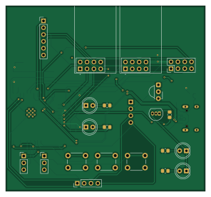
About the Litezero PCB
Litezero is an open source ESP32 PCB design by rudranshgoel1, published on GitHub. It is a 2-layer board measuring 73.9 × 68.6 mm, with 42 components from 25 distinct parts.
Its main chip is the ESP32-S3-WROOM-1, from the ESP32 family. Other key parts include the NRF24L01_BREAKOUT, AP2112K-3.3 and TSOP382XX. By type, the board carries 14 capacitors, 8 resistors, 7 connectors, 5 ICs, 4 diodes and 3 switches.
It belongs with the rf & radio, iot & wireless and displays & leds designs in this gallery.
From the project
- 2x NRF24L01 for 2.4ghz wireless stuff - 1x CC1101 for 433 mhz wireless stuff - 2 status LEDs - 2 IR LEDs (universal remote) - 3x tactile buttons to control - 1x 0.96 inch display for seeing what is going on - 1x inmp441 for voice commands - 1x sd card reader to store data - 1x
- 2x NRF24L01 for 2.4ghz wireless stuff - 1x CC1101 for 433 mhz wireless stuff - 2 status LEDs - 2 IR LEDs (universal remote) - 3x tactile buttons to control - 1x 0.96 inch display for seeing what is going on - 1x inmp441 for voice commands - 1x sd card reader to store data - 1x PN532 breakout board for NFC - ESP32 S3 WROOM1-N16R8 as the main brain
DISCLAIMER: This tool is intended for educational and research purposes only. I do not condone or endorse any illegal, malicious, or unauthorized use of this tool. Misuse includes, but is not limited to, unauthorized access to systems or networks…
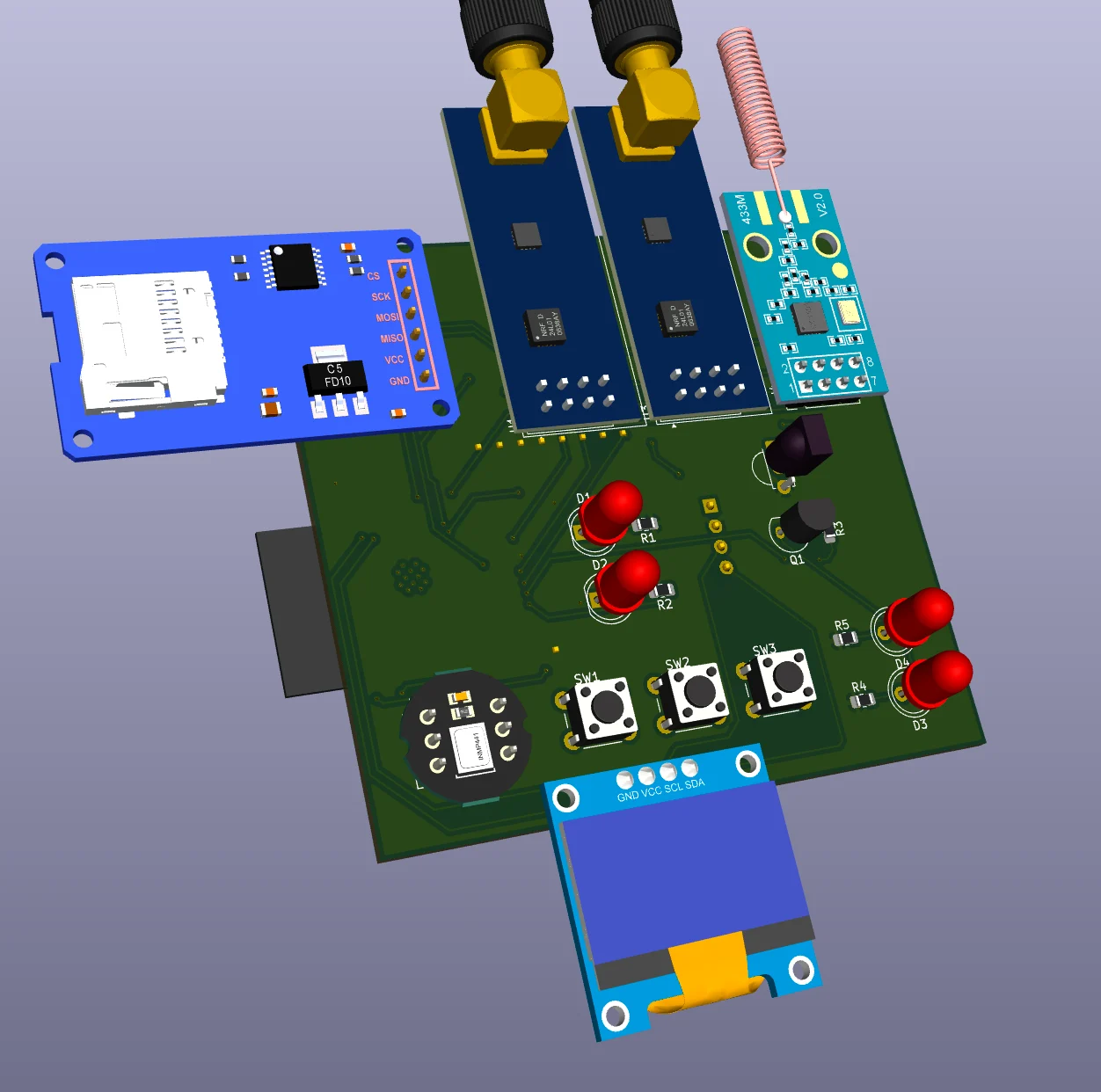
Main components on the Litezero
Litezero bill of materials (BOM)
42 components, 25 distinct parts — part numbers from the project's BOM.
| Qty | Part | Footprint | Refs |
|---|---|---|---|
| 2 | NRF24L01_BREAKOUT NRF24L01_Breakout | nRF24L01_Breakout | U1, U3 |
| 1 | AP2112K-3.3 | SOT-23-5 | U2 |
| 1 | TSOP382XX TSOP382xx | Vishay_MINICAST-3Pin | U4 |
| 1 | ESP32-S3-WROOM-1 | ESP32-S3-WROOM-1 | U6 |
| 1 | 2N3904 | TO-92_Inline | Q1 |
| 1 | 1.3 inch | PinHeader_1x04_P2.54mm_Vertical | J1 |
| 1 | USB_C_RECEPTACLE_USB2.0_14P USB_C_Receptacle_USB2.0_14P | USB_C_Receptacle_HRO_TYPE-C-31-M-12 | J2 |
| 2 | CONN_01X03 Conn_01x03 | PinHeader_1x03_P2.54mm_Vertical | J3, J5 |
| 1 | CC1101 cc1101 | PinHeader_2x04_P2.54mm_Vertical | J4 |
| 1 | PN532 pn532 | PinHeader_1x04_P2.54mm_Vertical | J7 |
| 1 | sd card reader | PinHeader_1x06_P2.54mm_Vertical | J8 |
| 1 | UP | SW_PUSH_6mm | SW1 |
| 1 | DOWN | SW_PUSH_6mm | SW2 |
| 1 | SELECT | SW_PUSH_6mm | SW3 |
| 1 | POWER | LED_D5.0mm | D1 |
| 1 | STATUS | LED_D5.0mm | D2 |
| 2 | LED | LED_D5.0mm | D3, D4 |
| 6 | 10UF 10uF | C_0805_2012Metric_Pad1.18x1.45mm_HandSolder | C1, C3, C5, C10, C12, C13 |
| 7 | 100NF 100nF | C_0805_2012Metric_Pad1.18x1.45mm_HandSolder | C2, C4, C6, C8, C9, C11, C14 |
| 1 | 22UF 22uF | C_0805_2012Metric_Pad1.18x1.45mm_HandSolder | C7 |
Show 5 more
| Qty | Part | Footprint | Refs |
|---|---|---|---|
| 2 | 220OHM 220ohm | R_0805_2012Metric_Pad1.20x1.40mm_HandSolder | R1, R2 |
| 1 | 1k ohm | R_0805_2012Metric_Pad1.20x1.40mm_HandSolder | R3 |
| 2 | 100 ohm | R_0805_2012Metric_Pad1.20x1.40mm_HandSolder | R4, R5 |
| 2 | 5.1KOHM 5.1kohm | R_0805_2012Metric_Pad1.20x1.40mm_HandSolder | R6, R7 |
| 1 | 10 kohm | R_0805_2012Metric_Pad1.20x1.40mm_HandSolder | R10 |
Litezero design files
The KiCad project lives in the rudranshgoel1/litezero repository on GitHub; these links point at the commit this page was built from.
- Layoutpcb/litezero.kicad_pcb
- Schematicpcb/litezero.kicad_sch
- BOMprod/pcb/litezero.csv
Litezero: common questions
What microcontroller does the Litezero use?
The Litezero is built around the ESP32-S3-WROOM-1, from the ESP32 family.
How big is the Litezero PCB?
The Litezero measures 73.9 × 68.6 mm, has 2 copper layers and is 1.6 mm thick.
How many components are on the Litezero?
42 components, from 25 distinct parts, with part numbers taken from the project's own BOM. The full bill of materials is listed on this page.
Where can I download the Litezero design files?
From the rudranshgoel1/litezero repository on GitHub, which has the KiCad layout, the schematic and the BOM; the links under Design files point to each one.
Can I use the Litezero design in my own project?
The repository has no license, so all rights stay with rudranshgoel1. Use it as a reference, and ask the author before reusing the design.
Can I test firmware for the Litezero without the hardware?
Yes. HardLabs builds a simulation of the board from its netlist and BOM, so you can run and debug ESP32 firmware against it before you order a PCB.
Similar boards
 ESP32
OSO-BOOK-B1
joeycastillo
85 × 115 mm65 parts2LCC-BY-SA-4.08.1k ESP32
Powertrain
byrantech
64 × 45.4 mm171 parts4LMIT4.3k ESP32
Badge
atopile
56.3 × 39 mm239 parts4LMIT4.0k ESP32
Esp32 minimal
36.2 × 26.8 mm20 parts2LMIT4.0k ESP32
Racer
StuckAtPrototype
36 × 50.2 mm70 parts4LApache-2.03.8k ESP32
Controller
29 × 74 mm58 parts4LApache-2.03.8k