
Kicad testing station

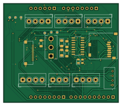
About the Kicad testing station PCB
Kicad testing station is an open source PCB design by solar-cooker-UHasselt, published on GitHub under the CC-BY-SA-4.0 license. It is a 4-layer board measuring 62.6 × 53.9 mm, with 72 components from 29 distinct parts.
Other key parts include the BME680, DS3231M+TRL, 74HC4050D, TBA 1-0519 and MAX31865ATP+. By type, the board carries 25 resistors, 14 diodes, 12 connectors, 9 capacitors, 7 ICs and 3 inductors.
It belongs with the sensors, power & battery and dev boards & breakouts designs in this gallery.
From the project
KiCad PCB for the solar cooker testing station: cooking temperature, weather and solar irradiance
The main board of the solar cooker testing station: a shield for the Arduino UNO R4 WiFi that logs how a solar cooker performs. With the firmware (arduino-code) it records:
- the temperature in three pots, with PT100 probes on three MAX31865 circuits - the solar irradiance, with a pyranometer - the wind speed, with an anemometer - the outside temperature, with an AM2315C sensor - the air pressure and humidity inside the box, with a BME680
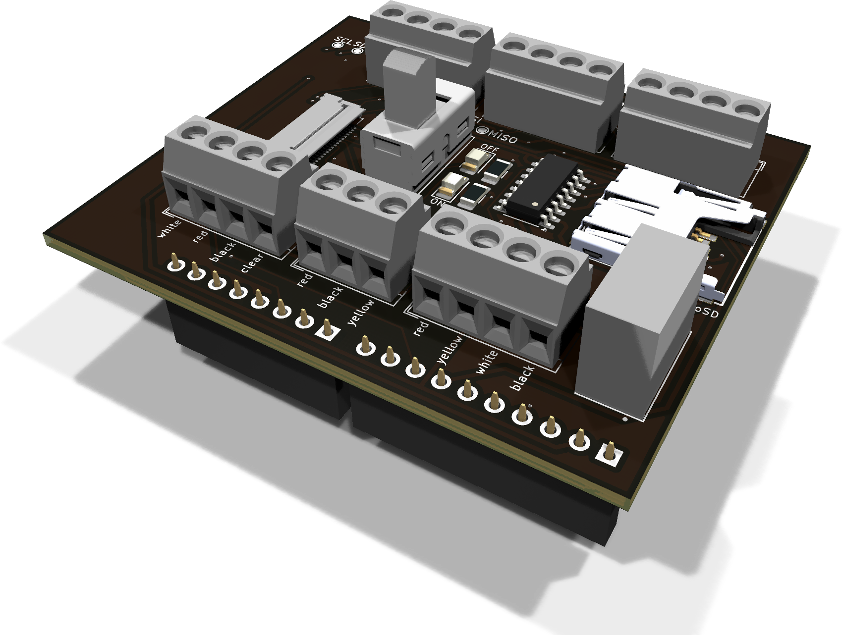
Main components on the Kicad testing station
Kicad testing station bill of materials (BOM)
72 components, 29 distinct parts.
| Qty | Part | Footprint | Refs |
|---|---|---|---|
| 1 | BME680 Bosch Sensortec | Bosch_LGA-8_3x3mm_P0.8mm_ClockwisePinNumbering | IC1 |
| 1 | DS3231M+TRL DS3231 Analog Devices Inc./Maxim Integrated | SOIC-16W_7.5x10.3mm_P1.27mm | IC2 |
| 1 | 74HC4050D Toshiba Semiconductor and Storage | SOIC-16_3.9x9.9mm_P1.27mm | IC3 |
| 1 | TBA 1-0519 TBA_1-0519 Traco Power | TBA_1-0519 | U1 |
| 3 | MAX31865ATP+ MAX31865 Analog Devices Inc./Maxim Integrated | MAX31865ATP+ | U2, U4, U6 |
| 1 | BSS138DWQ-7 BSS138 Diodes Incorporated | SOT-363_SC-70-6 | Q1 |
| 1 | 039357-0004 pyranometer Molex | TerminalBlock_4Ucon_1x04_P3.50mm_Horizontal | J1 |
| 1 | 039357-0003 anemometer Molex | TerminalBlock_4Ucon_1x03_P3.50mm_Horizontal | J2 |
| 1 | 039357-0004 AM2315C Molex | TerminalBlock_4Ucon_1x04_P3.50mm_Horizontal | J3 |
| 1 | XF2M-1815-1A FPC connector Omron Electronics Inc-EMC Div | XF2M-1815-1A | J4 |
| 3 | 039357-0004 Pt100 Molex | TerminalBlock_4Ucon_1x04_P3.50mm_Horizontal | J5, J7, J9 |
| 1 | SSQ-110-01-G-S Conn_01x10_Socket Samtec Inc. | PinSocket_1x10_P2.54mm_Vertical | J6 |
| 2 | SSQ-108-01-G-S Conn_01x08_Socket Samtec Inc. | PinSocket_1x08_P2.54mm_Vertical | J8, J11 |
| 1 | SSQ-106-01-G-S Conn_01x06_Socket Samtec Inc. | PinSocket_1x06_P2.54mm_Vertical | J10 |
| 1 | MEM2061-01-188-00-A microSD GCT | MEM2061-01-188-00-A | J13 |
| 1 | 500SSP1S2M2QEA E-switch | 500SSP1S2M2QEA | SW1 |
| 1 | 150120VS75000 LED_GREEN Würth Elektronik | LED_1206_3216Metric_Pad1.42x1.75mm_HandSolder | D1 |
| 1 | QTLP650D2TR LED_RED Everlight Electronics Co Ltd | LED_1206_3216Metric_Pad1.42x1.75mm_HandSolder | D2 |
| 10 | 1N4148WX-TP 1N4148 Micro Commercial Co | D_SOD-323 | D3, D4, D5, D6, D7, D8, D9, D10 +2 |
| 1 | 150060GS75000 GREEN Würth Elektronik | LED_0603_1608Metric | D12 |
Show 9 more
| Qty | Part | Footprint | Refs |
|---|---|---|---|
| 1 | 150080SS75000 RED Würth Elektronik | LED_0805_2012Metric | D14 |
| 3 | LI0805G201R-10 FERRITE-0805NO Laird-Signal Integrity Products | LI0805G201R-10 | FB1, FB2, FB3 |
| 9 | / 0.1uF / | C_0805_2012Metric | C1, C2, C3, C6, C7, C8, C11, C12 +1 |
| 1 | / 10k / | R_1206_3216Metric_Pad1.30x1.75mm_HandSolder | R1 |
| 2 | / 150 / | R_1206_3216Metric_Pad1.30x1.75mm_HandSolder | R2, R3 |
| 11 | / 10K / | R_0805_2012Metric | R4, R5, R6, R8, R9, R10, R12, R13 +3 |
| 3 | / 430Ω, ±0.1% / | R_0805_2012Metric | R7, R11, R15 |
| 7 | / 10k / | R_0603_1608Metric | R16, R17, R18, R19, R20, R21, R22 |
| 1 | / 1k / | R_0805_2012Metric | R25 |
Kicad testing station design files
The KiCad project lives in the solar-cooker-UHasselt/kicad-testing-station repository on GitHub; these links point at the commit this page was built from.
- Layouttesting-station.kicad_pcb
- Schematictesting-station.kicad_sch
Kicad testing station: common questions
How big is the Kicad testing station PCB?
The Kicad testing station measures 62.6 × 53.9 mm, has 4 copper layers and is 1.6 mm thick.
How many components are on the Kicad testing station?
72 components, from 29 distinct parts. The full bill of materials is listed on this page.
Where can I download the Kicad testing station design files?
From the solar-cooker-UHasselt/kicad-testing-station repository on GitHub, which has the KiCad layout and the schematic; the links under Design files point to each one.
Can I use the Kicad testing station design in my own project?
Yes, under the terms of its CC-BY-SA-4.0 license, which solar-cooker-UHasselt chose for the repository.
Similar boards
Sensor smd
scottbez1
40 × 20 mm5 parts2LApache-2.04.2k
Sensors
StuckAtPrototype
15.2 × 9 mm14 parts4LApache-2.03.8k
EinkPDA screen
TalismanDesign
95 × 54 mm27 parts2LApache-2.02.0k
Stack chan
stack-chan
50 × 50 mm33 parts2LApache-2.01.7k
Display Carrier
AxxAxx
35.6 × 58.2 mm5 parts2LGPL-3.01.7k
Microphone
Mentra-Community
5.5 × 6.1 mm6 parts2LMIT1.2k