
Dasduino-CONNECTPLUS-hardware design

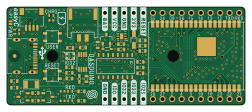
About the Dasduino-CONNECTPLUS-hardware design PCB
Dasduino-CONNECTPLUS-hardware design is an open source ESP32 PCB design by SolderedElectronics, published on GitHub under the TAPR-OHL-1.0 license. It is a 2-layer board measuring 63 × 25.9 mm, with 51 components from 31 distinct parts.
Its main chip is the ESP32-WROVER, from the ESP32 family. Other key parts include the CH340C, TPS7A2633DRVR and TP4056M. By type, the board carries 16 resistors, 11 capacitors, 6 diodes, 5 relays, 4 ICs and 3 transistors.
It belongs with the iot & wireless and power & battery designs in this gallery.
From the project
Hardware design, BOM, gerbers and 3D files for Dasduino-CONNECTPLUS designed by Soldered Electronics.
If you’re looking for a microcontroller simple-to-use, yet powerful enough for a wide variety of applications, look no further from our connectplus. From low-power sensor networks to demanding tasks such as streaming music, MP3 encoding, and voice recording, this microcontroller can do it all. Dasduino CONNECTPLUS comes with integrated Wi-Fi and Bluetooth 4.2, which enable low-energy secure connections with data packet length extensions. It uses the powerful ESP32 controller with 4 MB integrated flash and 8 MB integrated PSRAM.

Main components on the Dasduino-CONNECTPLUS-hardware design
Dasduino-CONNECTPLUS-hardware design bill of materials (BOM)
51 components, 31 distinct parts — part numbers from the project's BOM.
| Qty | Part | Footprint | Refs |
|---|---|---|---|
| 1 | CH340C | SOP-16 | U1 |
| 1 | ESP32-WROVER | ESP32-WROVER | U2 |
| 1 | TPS7A2633DRVR | TPS7A2633DRVR | U3 |
| 1 | TP4056M | TP4056M-MSOP8 | U4 |
| 1 | PMOS-SOT-23-3 | SOT-23-3 | Q1 |
| 2 | NPN-SOT-23-3 | SOT-23-3 | Q2, Q3 |
| 1 | 1206FUSE-500mA | 1206FUSE | F1 |
| 2 | HOLE_3.2mm | HOLE_3.2mm | H1, H3 |
| 1 | SMD-JUMPER-CONNECTED_TRACE_SLODERMASK | SMD-JUMPER-CONNECTED_TRACE_SLODERMASK | JP1 |
| 1 | U262-161N-4BVC11 | U262-161N-4BVC11 | K1 |
| 1 | easyC-SMD | easyC-connector | K2 |
| 1 | JST-2pin-SMD | JST-2pin-SMD | K3 |
| 2 | HEADER_MALE_15X1 | HEADER_MALE_15X1 | K4, K5 |
| 2 | YTSA007A0151803B | YTSA007A0151803B | SW1, SW2 |
| 1 | white | 0402LED | D1 |
| 1 | blue | 0402LED | D2 |
| 1 | purple | 0402LED | D3 |
| 1 | WS2812B-2020 | WS2812B-2020 | D4 |
| 1 | schottky diode | SOD-323 | D5 |
| 1 | red | 0402LED | D6 |
Show 11 more
| Qty | Part | Footprint | Refs |
|---|---|---|---|
| 1 | 10uF | 1206C | C1 |
| 2 | 1uF | 0603C | C2, C5 |
| 3 | 0.1uF | 0603C | C3, C4, C6 |
| 4 | 2.2uF | 0603C | C7, C8, C9, C10 |
| 1 | 100nF | 0603C | C11 |
| 5 | 10k | 0603R | R1, R10, R11, R12, R13 |
| 2 | 5.1k | 0603R | R2, R3 |
| 3 | 1k | 0603R | R4, R5, R17 |
| 4 | 2k2 | 0402R | R6, R7, R8, R15 |
| 1 | 100k | 0603R | R9 |
| 1 | 3k | 0603R | R14 |
Dasduino-CONNECTPLUS-hardware design design files
The KiCad project lives in the SolderedElectronics/Dasduino-CONNECTPLUS-hardware-design repository on GitHub; these links point at the commit this page was built from.
Dasduino-CONNECTPLUS-hardware design: common questions
What microcontroller does the Dasduino-CONNECTPLUS-hardware design use?
The Dasduino-CONNECTPLUS-hardware design is built around the ESP32-WROVER, from the ESP32 family.
How big is the Dasduino-CONNECTPLUS-hardware design PCB?
The Dasduino-CONNECTPLUS-hardware design measures 63 × 25.9 mm, has 2 copper layers and is 1.6 mm thick.
How many components are on the Dasduino-CONNECTPLUS-hardware design?
51 components, from 31 distinct parts, with part numbers taken from the project's own BOM. The full bill of materials is listed on this page.
Where can I download the Dasduino-CONNECTPLUS-hardware design design files?
From the SolderedElectronics/Dasduino-CONNECTPLUS-hardware-design repository on GitHub, which has the KiCad layout, the schematic and the BOM; the links under Design files point to each one.
Can I use the Dasduino-CONNECTPLUS-hardware design design in my own project?
Yes, under the terms of its TAPR-OHL-1.0 license, which SolderedElectronics chose for the repository.
Can I test firmware for the Dasduino-CONNECTPLUS-hardware design without the hardware?
Yes. HardLabs builds a simulation of the board from its netlist and BOM, so you can run and debug ESP32 firmware against it before you order a PCB.
Similar boards
 ESP32
ESP32Open Book Abridged Edition
joeycastillo
85 × 115 mm65 parts2LCC-BY-SA-4.08.1k ESP32
ESP32Badge
atopile
56.3 × 39 mm239 parts4LMIT4.0k ESP32
ESP32Esp32 minimal
36.2 × 26.8 mm20 parts2LMIT4.0k ESP32
ESP32Racer
StuckAtPrototype
36 × 50.2 mm70 parts4LApache-2.03.8k ESP32
ESP32Controller
29 × 74 mm58 parts4LApache-2.03.8k ESP32
ESP32Bitaxe
skot
56.5 × 99.8 mm86 parts4LCERN-OHL-S-2.01.4k