
ButtonLEDsController

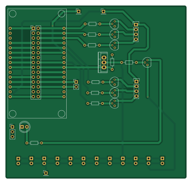
About the ButtonLEDsController PCB
ButtonLEDsController is an open source ESP8266 PCB design by spotlesscoder, published on GitHub under the CERN-OHL-1.2 license. It is a 2-layer board measuring 94 × 90 mm, with 39 components from 14 distinct parts.
Its main chip is the NodeMCU1.0(ESP-12E), from the ESP8266 family. By type, the board carries 15 diodes, 9 resistors, 8 transistors, 6 connectors and 1 IC.
It belongs with the displays & leds and dev boards & breakouts designs in this gallery.
From the project
This is part of the the hardware specification for my smart clock project.
This is part of the the hardware specification for my smart clock project.
The hardware consists of one device for the wake-up light functionality and another for the controls and LCD display.
The control unit with the display again, consists of 3 major parts held in one encasing
1.1) The controller for the input devices: various buttons and a PIR motion sensor. There are many buttons for quite a lot of different features. As the NodeMCU doesn't have enough pins, two PCF8574 IO expander chips are used (yes, I tried the MCP23017 but didn't like the libraries and didn't want to write a new…
Main components on the ButtonLEDsController
ButtonLEDsController bill of materials (BOM)
39 components, 14 distinct parts.
| Qty | Part | Footprint | Refs |
|---|---|---|---|
| 1 | NodeMCU1.0(ESP-12E) | NodeMCU1.0(12-E) | U1 |
| 1 | IRLZ34N | TO-220 | Q1 |
| 1 | Q_PNP_EBC | TO-92_Molded_Narrow | Q2 |
| 6 | Q_NPN_EBC | TO-92_Molded_Narrow | Q3, Q4, Q5, Q6, Q7, Q8 |
| 1 | Conn_02x15_Odd_Even | Pin_Header_Straight_2x15_Pitch2.54mm | J1 |
| 1 | Conn_01x03 | Pin_Header_Straight_1x03_Pitch2.54mm | J2 |
| 3 | Conn_01x01 | Pin_Header_Straight_1x01_Pitch2.54mm | J3, J4, J5 |
| 1 | Conn_01x02_Female | Socket_Strip_Straight_1x02_Pitch2.54mm | J6 |
| 13 | LED | LED_D5.0mm | D1, D2, D3, D4, D5, D6, D7, D8 +5 |
| 2 | LED_ARGB | Pin_Header_Straight_1x04 | D14, D15 |
| 1 | 10kR | R_Axial_DIN0204_L3.6mm_D1.6mm_P7.62mm_Horizontal | R1 |
| 1 | 10k | R_Axial_DIN0204_L3.6mm_D1.6mm_P7.62mm_Horizontal | R2 |
| 1 | 330 | R_Axial_DIN0204_L3.6mm_D1.6mm_P7.62mm_Horizontal | R3 |
| 6 | 1k | R_Axial_DIN0204_L3.6mm_D1.6mm_P7.62mm_Horizontal | R4, R5, R6, R7, R8, R9 |
ButtonLEDsController design files
The KiCad project lives in the spotlesscoder/SmartClockHardware_ControlUnit repository on GitHub; these links point at the commit this page was built from.
ButtonLEDsController: common questions
What microcontroller does the ButtonLEDsController use?
The ButtonLEDsController is built around the NodeMCU1.0(ESP-12E), from the ESP8266 family.
How big is the ButtonLEDsController PCB?
The ButtonLEDsController measures 94 × 90 mm, has 2 copper layers and is 1.6 mm thick.
How many components are on the ButtonLEDsController?
39 components, from 14 distinct parts. The full bill of materials is listed on this page.
Where can I download the ButtonLEDsController design files?
From the spotlesscoder/SmartClockHardware_ControlUnit repository on GitHub, which has the KiCad layout; the links under Design files point to each one.
Can I use the ButtonLEDsController design in my own project?
Yes, under the terms of its CERN-OHL-1.2 license, which spotlesscoder chose for the repository.
Can I test firmware for the ButtonLEDsController without the hardware?
Yes. HardLabs builds a simulation of the board from its netlist and BOM, so you can run and debug ESP8266 firmware against it before you order a PCB.
More boards in SmartClockHardware_ControlUnit
Similar boards
 ESP8266
ControllerCircuit
stuartpittaway
75 × 30 mm20 parts2LCC-BY-NC-4.01.1k ESP8266
HASwitchPlate
aderusha
60 × 40 mm8 parts2LMIT738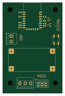 ESP8266
RatGDO-OpenSource-Bare-ESP8266
Kaldek
55 × 82.7 mm20 parts2LMIT506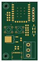 ESP8266
Goatgdo
32.9 × 53.3 mm23 parts2LMIT506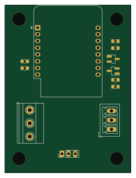 ESP8266
RatGDO-OpenSource-D1Mini-ESP8266
47.8 × 63.3 mm12 parts2LMIT506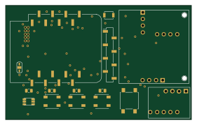 ESP8266
Iaq board
nkitanov
70.1 × 43.2 mm17 parts2LNo license398