
SERIAL PIC PROGRAMMER

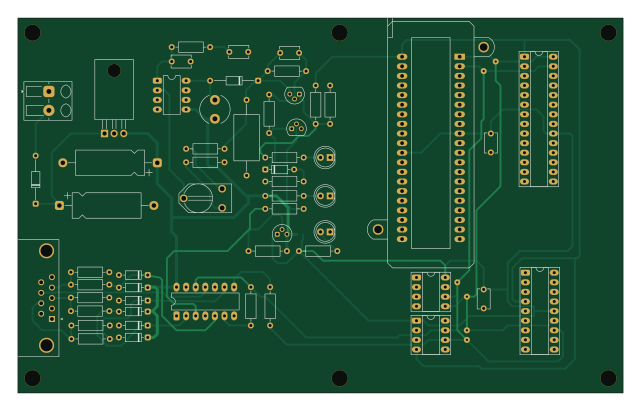
About the SERIAL PIC PROGRAMMER PCB
SERIAL PIC PROGRAMMER is an open source PIC PCB design by thisis-romar, published on GitHub. It is a 2-layer board measuring 160 × 99.1 mm, with 55 components from 35 distinct parts.
Its main chip is the PIC_18_PINS, from the PIC family. Other key parts include the 24Cxx, 74HC125, 7805, LT1373 and PIC_8_PINS. By type, the board carries 21 resistors, 12 diodes, 8 capacitors, 6 ICs, 3 transistors and 3 connectors.
It belongs with the usb & debug tools designs in this gallery.
From the project
Execution output of EMBLEM-NLP-RSPEC-001 v1.0.0 — Research Agent Specification: Laptop Electronics Drawing Type Discovery & Retrieval (Emblem Projects Inc., 2026-06-12).
Execution output of EMBLEM-NLP-RSPEC-001 v1.0.0 — Research Agent Specification: Laptop Electronics Drawing Type Discovery & Retrieval (Emblem Projects Inc., 2026-06-12).
This corpus retrieves the single most accurate, highest-authority publicly available example of each drawing type used in laptop electronics design, manufacturing, and repair. Every example is traceable to a named standards body, OEM technical document, or verified open-hardware repository. Generic diagrams, marketing infographics, AI-generated images, and DMCA-risk OEM schematic mirrors are explicitly excluded.
Main components on the SERIAL PIC PROGRAMMER
SERIAL PIC PROGRAMMER bill of materials (BOM)
55 components, 35 distinct parts — part numbers from the project's BOM.
| Qty | Part | Footprint | Refs |
|---|---|---|---|
| 1 | 24Cxx | DIP-8_W7.62mm_Socket_LongPads | U1 |
| 1 | 74HC125 | DIP-14_W7.62mm_LongPads | U2 |
| 1 | 7805 | TO-220-3_Horizontal_TabDown | U3 |
| 1 | LT1373 | DIP-8_W7.62mm_LongPads | U4 |
| 1 | PIC_18_PINS | DIP-18_W7.62mm_Socket_LongPads | U5 |
| 1 | PIC_8_PINS | DIP-8_W7.62mm_Socket_LongPads | U6 |
| 1 | BC237 | TO-92 | Q1 |
| 2 | BC307 | TO-92 | Q2, Q3 |
| 1 | CONN_2 | Altech_AK300_1x02_P5.00mm_45-Degree | P1 |
| 1 | SUPP28 | DIP-28_W7.62mm_Socket_LongPads | P2 |
| 1 | SUPP40 | 40tex-Ell600 | P3 |
| 1 | 1K | RV2X4 | RV1 |
| 1 | 1N4004 | D_DO-35_SOD27_P12.70mm_Horizontal | D1 |
| 7 | BAT43 | D_DO-35_SOD27_P7.62mm_Horizontal | D2, D3, D4, D5, D6, D7, D11 |
| 1 | RED-LED | LED_D5.0mm | D8 |
| 1 | GREEN-LED | LED_D5.0mm | D9 |
| 1 | SCHOTTKY | D_DO-35_SOD27_P12.70mm_Horizontal | D10 |
| 1 | YELLOW-LED | LED_D5.0mm | D12 |
| 1 | 22uH | L_Radial_D7.8mm_P5.00mm_Fastron_07HCP | L1 |
| 1 | 100µF | CP_Axial_L18.0mm_D6.5mm_P25.00mm_Horizontal | C1 |
Show 15 more
| Qty | Part | Footprint | Refs |
|---|---|---|---|
| 1 | 220uF | CP_Axial_L18.0mm_D6.5mm_P25.00mm_Horizontal | C2 |
| 1 | 22uF/25V | C_Axial_L12.0mm_D6.5mm_P20.00mm_Horizontal | C3 |
| 1 | 0 | C_Disc_D5.1mm_W3.2mm_P5.00mm | C4 |
| 1 | 10nF | C_Disc_D5.1mm_W3.2mm_P5.00mm | C5 |
| 2 | 100nF | C_Disc_D5.1mm_W3.2mm_P5.00mm | C6, C7 |
| 1 | 220nF | C_Disc_D5.1mm_W3.2mm_P5.00mm | C9 |
| 7 | 10K | R_Axial_DIN0207_L6.3mm_D2.5mm_P10.16mm_Horizontal | R1, R2, R3, R4, R5, R6, R7 |
| 1 | 1K | R_Axial_DIN0207_L6.3mm_D2.5mm_P10.16mm_Horizontal | R8 |
| 3 | 2.2K | R_Axial_DIN0207_L6.3mm_D2.5mm_P10.16mm_Horizontal | R9, R19, R20 |
| 1 | 5,1K | R_Axial_DIN0207_L6.3mm_D2.5mm_P10.16mm_Horizontal | R10 |
| 2 | 22K | R_Axial_DIN0207_L6.3mm_D2.5mm_P10.16mm_Horizontal | R11, R17 |
| 4 | 470 | R_Axial_DIN0207_L6.3mm_D2.5mm_P10.16mm_Horizontal | R12, R13, R14, R21 |
| 1 | 6.2K | R_Axial_DIN0207_L6.3mm_D2.5mm_P10.16mm_Horizontal | R15 |
| 1 | 62K | R_Axial_DIN0207_L6.3mm_D2.5mm_P10.16mm_Horizontal | R16 |
| 1 | 220 | R_Axial_DIN0207_L6.3mm_D2.5mm_P10.16mm_Horizontal | R18 |
SERIAL PIC PROGRAMMER design files
The KiCad project lives in the thisis-romar/drawing-corpus repository on GitHub; these links point at the commit this page was built from.
SERIAL PIC PROGRAMMER: common questions
What microcontroller does the SERIAL PIC PROGRAMMER use?
The SERIAL PIC PROGRAMMER is built around the PIC_18_PINS, from the PIC family.
How big is the SERIAL PIC PROGRAMMER PCB?
The SERIAL PIC PROGRAMMER measures 160 × 99.1 mm, has 2 copper layers and is 1.6 mm thick.
How many components are on the SERIAL PIC PROGRAMMER?
55 components, from 35 distinct parts, with part numbers taken from the project's own BOM. The full bill of materials is listed on this page.
Where can I download the SERIAL PIC PROGRAMMER design files?
From the thisis-romar/drawing-corpus repository on GitHub, which has the KiCad layout, the schematic and the BOM; the links under Design files point to each one.
Can I use the SERIAL PIC PROGRAMMER design in my own project?
The repository has no license, so all rights stay with thisis-romar. Use it as a reference, and ask the author before reusing the design.
Can I test firmware for the SERIAL PIC PROGRAMMER without the hardware?
Yes. HardLabs builds a simulation of the board from its netlist and BOM, so you can run and debug PIC firmware against it before you order a PCB.
More boards in drawing-corpus
Similar boards
 PIC
PICPslab hardware
fossasia
99 × 53.3 mm187 parts4LApache-2.01.7k PIC
PICMicro 8088
skiselev
152.4 × 101.6 mm71 partsGPL-3.0414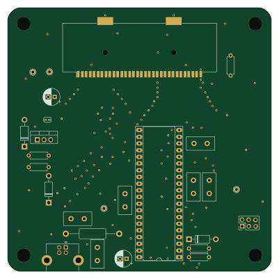 PIC
PICGB-CARTPP-DIY
Gekkio
100 × 100 mm22 parts2LCC-BY-4.0376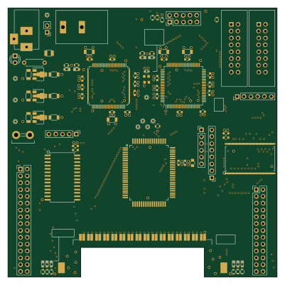 PIC
PICGB-BENCH-G1
100 × 100 mm98 parts4LCC-BY-4.0376 PIC
PICGB-MBCTEST
51.4 × 61 mm32 parts2LCC-BY-4.0376 PIC
PICGB-LIVE32
51.4 × 61 mm46 parts4LCC-BY-4.0376