
9 open source boards using the PIC_18_PINS
Real designs built with the PIC_18_PINS, from public GitHub projects: a quick way to see how others power, decouple and connect it. Each board comes with its KiCad files, full parts list and a render — and you can simulate its firmware on HardLabs.
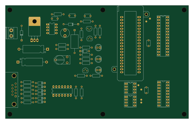
SERIAL PIC PROGRAMMER
zymaxcii
160 × 99.1 mm55 partsNo license1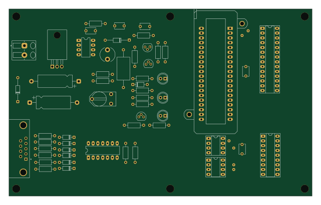 PIC
SERIAL PIC PROGRAMMER
thisis-romar
160 × 99.1 mm55 parts2LNo license0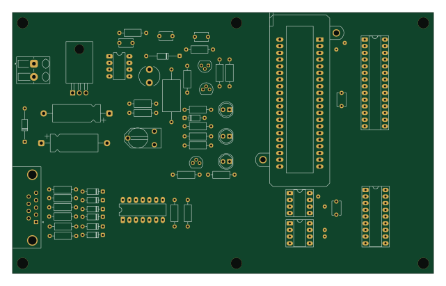
SERIAL PIC PROGRAMMER
Mhamednoui
160 × 99.1 mm55 parts2LNo license0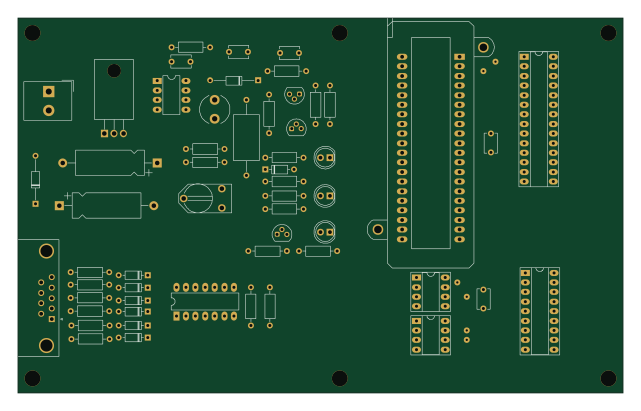
SERIAL PIC PROGRAMMER
palginpav
160 × 99.1 mm55 parts2LApache-2.01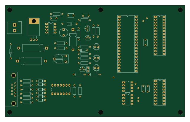
Flat hierarchy
circuitly
160 × 99.1 mm57 parts2LNo license0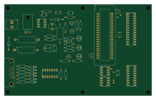
Pic programmer
160 × 99.1 mm56 parts2LNo license0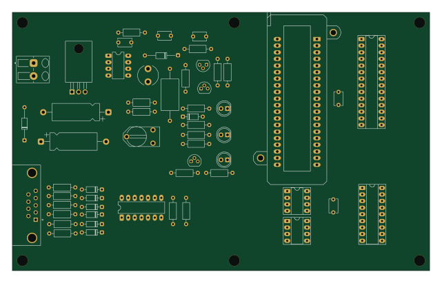
SERIAL PIC PROGRAMMER
claynicholson
160 × 99.1 mm55 parts2LMIT102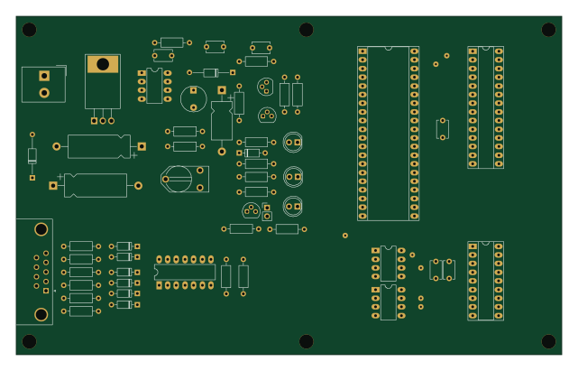 PIC
Flat hierarchy
nickradfc
160 × 99.1 mm57 parts2LNo license0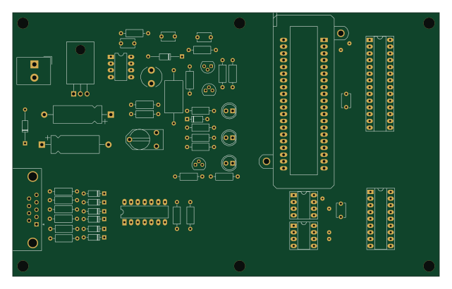 PIC
Pic programmer
160 × 99.1 mm55 parts2LNo license0
How designs wire the PIC_18_PINS
Read from the KiCad layouts of 7 open source designs, one per repository: what each pin of the PIC_18_PINS connects to, and the resistors, capacitors and other passives placed on it.
- The MCLR_4 pin has a series resistor on 7 of 7 designs, most often 220 Ω.
- The ICSPC/RB6_12 pin has a series resistor on 7 of 7 designs, most often 470 Ω.
- The ICSPD/RB7_13 pin has a series resistor on 7 of 7 designs, most often 470 Ω.
- The RA2_1 pin is left unconnected on 7 of 7 designs.
| Pin | Connected to | Parts on the pin |
|---|---|---|
| RA2_1pin 1 | Connected to: Not connected 100% | — |
| RA3_2pin 2 | Connected to: Not connected 100% | — |
| T0CKL_3pin 3 | Connected to: Not connected 100% | — |
| MCLR_4pin 4 | Connected to: PIC_8_PINS 100%, a connector 100% |
|
| VSS_5pin 5 | Connected to: GND 100% | — |
| RB0_6pin 6 | Connected to: Not connected 100% | — |
| RB1_7pin 7 | Connected to: Not connected 100% | — |
| RB2_8pin 8 | Connected to: Not connected 100% | — |
| RB3_9pin 9 | Connected to: Not connected 100% | — |
| RB4_10pin 10 | Connected to: Not connected 100% | — |
| RB5_11pin 11 | Connected to: Not connected 100% | — |
| ICSPC/RB6_12pin 12 | Connected to: PIC_8_PINS 100%, a connector 100%, 24Cxx 71% |
|
| ICSPD/RB7_13pin 13 | Connected to: PIC_8_PINS 100%, 74HC125 86%, 24Cxx 71% |
|
| VDD_14pin 14 | Connected to: VCC_PIC 100% | — |
| OSC2/CLKO_15pin 15 | Connected to: Not connected 100% | — |
| OSC1/CLKI_16pin 16 | Connected to: Not connected 100% | — |
| RA0_17pin 17 | Connected to: Not connected 100% | — |
| RA1_18pin 18 | Connected to: Not connected 100% | — |
Connections count pins, parts count designs; values in brackets are how many parts had that value. Designs read include SERIAL PIC PROGRAMMER by claynicholson, SERIAL PIC PROGRAMMER by palginpav, SERIAL PIC PROGRAMMER by zymaxcii and Flat hierarchy by circuitly.
The PIC_18_PINS in open source designs
The gallery holds 9 open source boards using the PIC_18_PINS from 7 GitHub repositories; a typical one measures about 160 × 99.1 mm and carries around 55 components.
100% are two-layer designs, the rest use four layers or more, and 22% carry an open source license.
The most starred is SERIAL PIC PROGRAMMER by claynicholson.
Parts used alongside the PIC_18_PINS
Microcontrollers on boards using the PIC_18_PINS
What boards using the PIC_18_PINS are built for
PIC_18_PINS: common questions
Where can I find a PIC_18_PINS reference design?
Each of the 9 boards on this page is a real design using the PIC_18_PINS. Open one to see how it is wired up, with the full BOM, a render of the layout and links to its KiCad files.
What resistor goes on the PIC_18_PINS MCLR_4 pin?
The MCLR_4 pin has a series resistor on 7 of 7 designs, most often 220 Ω. Counted from the KiCad layouts of 7 open source designs using the PIC_18_PINS.
What resistor goes on the PIC_18_PINS ICSPC/RB6_12 pin?
The ICSPC/RB6_12 pin has a series resistor on 7 of 7 designs, most often 470 Ω. Counted from the KiCad layouts of 7 open source designs using the PIC_18_PINS.
What resistor goes on the PIC_18_PINS ICSPD/RB7_13 pin?
The ICSPD/RB7_13 pin has a series resistor on 7 of 7 designs, most often 470 Ω. Counted from the KiCad layouts of 7 open source designs using the PIC_18_PINS.
What parts are used alongside the PIC_18_PINS?
The LT1373, PIC_8_PINS, 74HC125, 7805 and 24Cxx appear in the most repositories here.
Which microcontrollers do boards using the PIC_18_PINS use?
Most are built on PIC (3).
How big is a typical board using the PIC_18_PINS?
The median is 160 × 99.1 mm, and 100% are two-layer designs.
What is the most popular open source board using the PIC_18_PINS?
By GitHub stars, SERIAL PIC PROGRAMMER by claynicholson, with 102 stars.
Can I simulate one of these boards using the PIC_18_PINS before building it?
Yes. HardLabs turns a board's netlist and BOM into a working simulation, so you can boot and test firmware against it with no hardware on your desk.