
Flight computer

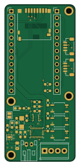
About the Flight computer PCB
Flight computer is an open source PCB design by unl-rocketry, published on GitHub under the CERN-OHL-S-2.0 license. It is a 2-layer board measuring 27 × 60 mm, with 32 components from 19 distinct parts.
Other key parts include the CPC1002N, BME280, BNO055 and TPS62172DSG. By type, the board carries 11 resistors, 7 connectors, 6 ICs, 3 capacitors, 2 diodes and 1 crystal.
It belongs with the sensors and robotics & motion designs in this gallery.
From the project
An experimental flight controller/altimeter board family developed by UNL Aerospace Rocketry
All designs in this repository are licensed under the CERN-OHL-S v2 or any later version. Contributions are welcome!
The connectors on the Core Board are compatible with any Adafruit Stemma QT or SparkFun Qwiic board, which immediately provides for a lot of options for sensors without any design or soldering work needed.
In the future, this repository will host the KiCad files for expansion boards created by UNL Aerospace Rocketry.
Main components on the Flight computer
Flight computer bill of materials (BOM)
32 components, 19 distinct parts.
| Qty | Part | Footprint | Refs |
|---|---|---|---|
| 3 | CPC1002N | SOP-4_3.8x4.1mm_P2.54mm | U1, U2, U3 |
| 1 | BME280 | Bosch_LGA-8_2.5x2.5mm_P0.65mm_ClockwisePinNumbering | U4 |
| 1 | BNO055 | LGA-28_5.2x3.8mm_P0.5mm | U5 |
| 1 | TPS62172DSG | WSON-8-1EP_2x2mm_P0.5mm_EP0.9x1.6mm_ThermalVias | U6 |
| 1 | 32.768kHz | Crystal_SMD_G8-2Pin_3.2x1.5mm_HandSoldering | Y1 |
| 2 | Conn_01x13_Socket | PinHeader_1x13_P2.54mm_Vertical | J1, J2 |
| 1 | Ignitor Output | TerminalBlock_Phoenix_MPT-0,5-4-2.54_1x04_P2.54mm_Horizontal | J3 |
| 1 | Micro_SD_Card | microSD_HC_Hirose_DM3D-SF | J4 |
| 1 | Battery Input | JST_PH_S2B-PH-K_1x02_P2.00mm_Horizontal | J5 |
| 1 | Connector 1 | JST_SH_BM04B-SRSS-TB_1x04-1MP_P1.00mm_Vertical-CUSTOM | J7 |
| 1 | Connector 2 | JST_SH_BM04B-SRSS-TB_1x04-1MP_P1.00mm_Vertical-CUSTOM | J8 |
| 1 | 10µF | C_0805_2012Metric_Pad1.18x1.45mm_HandSolder | f1 |
| 1 | D | D_0603_1608Metric_Pad1.05x0.95mm_HandSolder | D1 |
| 1 | LED | LED_0603_1608Metric_Pad1.05x0.95mm_HandSolder | D2 |
| 1 | 2.2µH | L_0603_1608Metric_Pad1.05x0.95mm_HandSolder | L1 |
| 2 | 22pF | C_0603_1608Metric_Pad1.08x0.95mm_HandSolder | C1, C2 |
| 1 | 0.1µF | C_0603_1608Metric_Pad1.08x0.95mm_HandSolder | C3 |
| 8 | 4.4k | R_0603_1608Metric_Pad0.98x0.95mm_HandSolder | R1, R2, R3, R4, R5, R7, R10, R11 |
| 3 | 10k | R_0603_1608Metric_Pad0.98x0.95mm_HandSolder | R6, R8, R9 |
Flight computer design files
The KiCad project lives in the unl-rocketry/flight-computer repository on GitHub; these links point at the commit this page was built from.
Flight computer: common questions
How big is the Flight computer PCB?
The Flight computer measures 27 × 60 mm, has 2 copper layers and is 1.6 mm thick.
How many components are on the Flight computer?
32 components, from 19 distinct parts. The full bill of materials is listed on this page.
Where can I download the Flight computer design files?
From the unl-rocketry/flight-computer repository on GitHub, which has the KiCad layout and the schematic; the links under Design files point to each one.
Can I use the Flight computer design in my own project?
Yes, under the terms of its CERN-OHL-S-2.0 license, which unl-rocketry chose for the repository.
Similar boards

Sensor smd
scottbez1
40 × 20 mm5 parts2LApache-2.04.2k
Sensors
StuckAtPrototype
15.2 × 9 mm14 parts4LApache-2.03.8k
Stack chan
stack-chan
50 × 50 mm33 parts2LApache-2.01.7k
Microphone
Mentra-Community
5.5 × 6.1 mm6 parts2LMIT1.2k
TemperaturePCB PANEL
stuartpittaway
116 × 75.5 mm178 parts2LCC-BY-NC-4.01.1k
Cube batteryboard
willem-pennings
95 × 95 mm4 parts2LGPL-3.01.1k