
Smart home

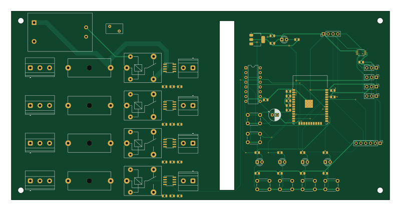
About the Smart home PCB
Smart home is an open source ESP32 PCB design by vishal007-hacker, published on GitHub under the MIT license. It is a 2-layer board measuring 200 × 100 mm, with 76 components from 35 distinct parts.
Its main chip is the ESP32-WROOM-32E-N4, from the ESP32 family. Other key parts include the ULN2003AN, AMS1117-3.3, ACS712ELCTR-05B-T and ADS1115IDGSR. By type, the board carries 21 resistors, 14 connectors, 12 capacitors, 8 ICs, 6 switches and 5 diodes.
It belongs with the iot & wireless, displays & leds and power & battery designs in this gallery.
From the project
ESP32-based smart home controller for switching 4 independent 230V AC loads, with per-channel current and voltage sensing, manual override buttons, status LEDs, and an I²C LCD display.
ESP32-based smart home controller for switching 4 independent 230V AC loads, with per-channel current and voltage sensing, manual override buttons, status LEDs, and an I²C LCD display.
The project is a complete KiCad 9 design — schematic, PCB layout, BOM, custom symbol/footprint for the HLK-PM01 AC-DC module, custom DRC rules for mains clearance, and Python generator scripts that build everything from a single bom.csv.
Main components on the Smart home
Smart home bill of materials (BOM)
76 components, 35 distinct parts — part numbers from the project's BOM.
| Qty | Part | Footprint | Refs |
|---|---|---|---|
| 1 | ESP32-WROOM-32E-N4 ESP32-WROOM-32E | ESP32-WROOM-32 | U1 |
| 1 | ULN2003AN ULN2003A | DIP-16_W7.62mm | U2 |
| 1 | AMS1117-3.3 | SOT-223-3_TabPin2 | U3 |
| 4 | ACS712ELCTR-05B-T ACS712-05B | SOIC-8_3.9x4.9mm_P1.27mm | U4, U5, U6, U7 |
| 1 | ADS1115IDGSR ADS1115 | TSSOP-10_3x3mm_P0.5mm | U8 |
| 1 | AC_IN_1 | TerminalBlock_Phoenix_MKDS-1,5-3-5.08_1x03_P5.08mm_Horizontal | J1A |
| 1 | AC_IN_2 | TerminalBlock_Phoenix_MKDS-1,5-3-5.08_1x03_P5.08mm_Horizontal | J1B |
| 1 | AC_IN_3 | TerminalBlock_Phoenix_MKDS-1,5-3-5.08_1x03_P5.08mm_Horizontal | J1C |
| 1 | AC_IN_4 | TerminalBlock_Phoenix_MKDS-1,5-3-5.08_1x03_P5.08mm_Horizontal | J1D |
| 1 | LOAD_1 | TerminalBlock_Phoenix_MKDS-1,5-2-5.08_1x02_P5.08mm_Horizontal | J2A |
| 1 | LOAD_2 | TerminalBlock_Phoenix_MKDS-1,5-2-5.08_1x02_P5.08mm_Horizontal | J2B |
| 1 | LOAD_3 | TerminalBlock_Phoenix_MKDS-1,5-2-5.08_1x02_P5.08mm_Horizontal | J2C |
| 1 | LOAD_4 | TerminalBlock_Phoenix_MKDS-1,5-2-5.08_1x02_P5.08mm_Horizontal | J2D |
| 1 | M20-9990645 PROG | PinHeader_1x06_P2.54mm_Vertical | J3 |
| 1 | M20-9990445 LCD I2C | PinHeader_1x04_P2.54mm_Vertical | J4 |
| 1 | M20-9990345 V_SENSE_1 | PinHeader_1x03_P2.54mm_Vertical | J5 |
| 1 | M20-9990345 V_SENSE_2 | PinHeader_1x03_P2.54mm_Vertical | J6 |
| 1 | M20-9990345 V_SENSE_3 | PinHeader_1x03_P2.54mm_Vertical | J7 |
| 1 | M20-9990345 V_SENSE_4 | PinHeader_1x03_P2.54mm_Vertical | J8 |
| 4 | 0034.3122 T4A | Fuseholder_Cylinder-5x20mm_Schurter_0031_8201_Horizontal_Open | F1, F2, F3, F4 |
Show 15 more
| Qty | Part | Footprint | Refs |
|---|---|---|---|
| 4 | SRD-05VDC-SL-C | Relay_SPDT_SANYOU_SRD_Series_Form_C | K1, K2, K3, K4 |
| 1 | HLK-PM01 | HLK-PM01 | PS1 |
| 1 | S07K275 | RV_Disc_D9mm_W5.2mm_P5mm | RV1 |
| 6 | TS-1102-G TACT_6mm | SW_PUSH_6mm | SW1, SW2, SW3, SW4, SW5, SW6 |
| 4 | LTL-4231N LED_Green | LED_D3.0mm | D1, D2, D3, D4 |
| 1 | LTL-4221N LED_Red | LED_D3.0mm | D5 |
| 1 | UVR1C101MED1TD 100uF/16V | CP_Radial_D6.3mm_P2.50mm | C1 |
| 2 | CL21A106KOQNNNE 10uF | C_0805_2012Metric | C2, C4 |
| 1 | CL21A226MQQNNNE 22uF | C_0805_2012Metric | C3 |
| 7 | CL21B104KBCNNNC 100nF | C_0805_2012Metric | C5, C7, C8, C9, C10, C11, C16 |
| 1 | CL21B105KAFNNNE 1uF | C_0805_2012Metric | C6 |
| 5 | RC0805FR-071KL 1k | R_0805_2012Metric | R1, R2, R3, R4, R9 |
| 10 | RC0805FR-0710KL 10k | R_0805_2012Metric | R5, R6, R7, R8, R11, R12, R15, R16 +2 |
| 2 | RC0805FR-074K7L 4.7k | R_0805_2012Metric | R13, R14 |
| 4 | RC0805FR-0718KL 18k | R_0805_2012Metric | R19, R20, R21, R22 |
Smart home design files
The KiCad project lives in the vishal007-hacker/smart-home repository on GitHub; these links point at the commit this page was built from.
- Layoutsmart_home.kicad_pcb
- Schematicsmart_home.kicad_sch
- BOMbom.csv
Smart home: common questions
What microcontroller does the Smart home use?
The Smart home is built around the ESP32-WROOM-32E-N4, from the ESP32 family.
How big is the Smart home PCB?
The Smart home measures 200 × 100 mm, has 2 copper layers and is 1.6 mm thick.
How many components are on the Smart home?
76 components, from 35 distinct parts, with part numbers taken from the project's own BOM. The full bill of materials is listed on this page.
Where can I download the Smart home design files?
From the vishal007-hacker/smart-home repository on GitHub, which has the KiCad layout, the schematic and the BOM; the links under Design files point to each one.
Can I use the Smart home design in my own project?
Yes, under the terms of its MIT license, which vishal007-hacker chose for the repository.
Can I test firmware for the Smart home without the hardware?
Yes. HardLabs builds a simulation of the board from its netlist and BOM, so you can run and debug ESP32 firmware against it before you order a PCB.
Similar boards
 ESP32
ESP32Open Book Abridged Edition
joeycastillo
85 × 115 mm65 parts2LCC-BY-SA-4.08.1k ESP32
ESP32Esp32 minimal
atopile
36.2 × 26.8 mm20 parts2LMIT4.0k ESP32
ESP32Badge
56.3 × 39 mm239 parts4LMIT4.0k ESP32
ESP32Controller
StuckAtPrototype
29 × 74 mm58 parts4LApache-2.03.8k ESP32
ESP32Racer
36 × 50.2 mm70 parts4LApache-2.03.8k ESP32
ESP32Bitaxe
skot
56.5 × 99.8 mm86 parts4LCERN-OHL-S-2.01.4k