
Raspberry Pi Pico Logger - Relay

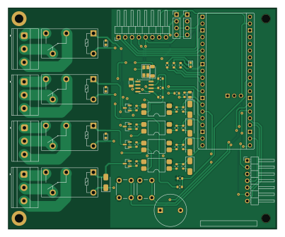
About the Raspberry Pi Pico Logger - Relay PCB
Raspberry Pi Pico Logger - Relay is an open source Raspberry Pi PCB design by WestianPKl, published on GitHub. It is a 2-layer board measuring 100.5 × 83 mm, with 77 components from 34 distinct parts.
Its main chip is the RaspberryPi_Pico_W, from the Raspberry Pi family. Other key parts include the LTV-817S-TA1-C and MCP7940N-xSN. By type, the board carries 22 resistors, 15 capacitors, 12 diodes, 8 connectors, 5 ICs and 5 transistors.
It belongs with the power & battery designs in this gallery.
From the project
A collection of custom PCB designs created in KiCAD, centered around the Raspberry Pi Pico (RP2040) platform. Each board is a standalone module that connects to the Main Board and extends its functionality via I2C, SPI, or UART.
A collection of custom PCB designs created in KiCAD, centered around the Raspberry Pi Pico (RP2040) platform. Each board is a standalone module that connects to the Main Board and extends its functionality via I2C, SPI, or UART.
Author: Piotr Kłyś Tool: KiCAD 8.x Firmware: MicroPython (Pico boards), AVR-GCC (ATmega boards)
The central development and integration board built around the Raspberry Pi Pico. Used to test all peripheral modules in the collection.
Main components on the Raspberry Pi Pico Logger - Relay
Raspberry Pi Pico Logger - Relay bill of materials (BOM)
77 components, 34 distinct parts.
| Qty | Part | Footprint | Refs |
|---|---|---|---|
| 4 | LTV-817S-TA1-C | SMDIP-4_W9.53mm | U1, U2, U3, U4 |
| 1 | MCP7940N-xSN | SOIC-8_3.9x4.9mm_P1.27mm | U5 |
| 1 | RaspberryPi_Pico_W | RaspberryPi_Pico_Common_Unspecified | A1 |
| 4 | BC847B-DIO | SOT-23 | Q1, Q2, Q3, Q4 |
| 1 | BC817-40-DIO | SOT-23 | Q5 |
| 1 | QT3CD-32.768KEZY-T | Crystal_SMD_3215-2Pin_3.2x1.5mm | Y1 |
| 1 | Sensor | PinHeader_1x04_P2.54mm_Vertical | J1 |
| 1 | LCD 16x2 | PinHeader_1x04_P2.54mm_Vertical | J2 |
| 1 | Additional connector | PinHeader_1x08_P2.54mm_Horizontal | J3 |
| 1 | SPI | PinHeader_1x07_P2.54mm_Horizontal | J4 |
| 1 | ARK KF301 raster 5.0mm 3 pin | TerminalBlock_Phoenix_MKDS-1,5-3_1x03_P5.00mm_Horizontal | J5 |
| 3 | ARK KF301 raster 5,0mm 3 pin | TerminalBlock_Phoenix_MKDS-1,5-3_1x03_P5.00mm_Horizontal | J6, J7, J8 |
| 1 | CR2032 | BatteryHolder_Keystone_104_1x23mm | BT1 |
| 1 | Buzzer 5V 12mm | Buzzer_12x9.5RM7.6 | BZ1 |
| 4 | G5Q-14-EU-5DC | Relay_SPDT_Omron-G5Q-1 | K1, K2, K3, K4 |
| 2 | Tact Switch 6x6mm / 13mm | SW_PUSH_6mm | SW1, SW2 |
| 4 | 1N4007 M7 | D_SMA | D1, D2, D3, D4 |
| 4 | LED | LED_0603_1608Metric | D5, D6, D7, D8 |
| 1 | M7-DIO | D_SMA | D9 |
| 1 | OSTBPCS2C2B | LED_Avago_PLCC4_3.2x2.8mm_CW | D10 |
Show 14 more
| Qty | Part | Footprint | Refs |
|---|---|---|---|
| 1 | LL4148-DIO | D_MiniMELF | D11 |
| 1 | LED | LED_0805_2012Metric | D12 |
| 9 | 100nF | C_0603_1608Metric | C1, C3, C5, C7, C9, C12, C13, C14 +1 |
| 4 | 1uF | C_0603_1608Metric | C2, C4, C6, C8 |
| 2 | 12pF | C_0603_1608Metric | C10, C11 |
| 4 | 2k2R | R_0603_1608Metric | R1, R2, R7, R8 |
| 4 | 680R | R_0603_1608Metric | R3, R4, R9, R10 |
| 4 | 10kR | R_0603_1608Metric | R5, R6, R11, R12 |
| 3 | 4k7R | R_0603_1608Metric | R13, R14, R15 |
| 1 | 200kR | R_0603_1608Metric | R16 |
| 1 | 68kR | R_0603_1608Metric | R17 |
| 1 | 0R | R_0603_1608Metric | R18 |
| 1 | 1kR | R_0603_1608Metric | R19 |
| 3 | 330R | R_0603_1608Metric | R20, R21, R22 |
Raspberry Pi Pico Logger - Relay design files
The KiCad project lives in the WestianPKl/pcb-docs repository on GitHub; these links point at the commit this page was built from.
Raspberry Pi Pico Logger - Relay: common questions
What microcontroller does the Raspberry Pi Pico Logger - Relay use?
The Raspberry Pi Pico Logger - Relay is built around the RaspberryPi_Pico_W, from the Raspberry Pi family.
How big is the Raspberry Pi Pico Logger - Relay PCB?
The Raspberry Pi Pico Logger - Relay measures 100.5 × 83 mm, has 2 copper layers and is 1.6 mm thick.
How many components are on the Raspberry Pi Pico Logger - Relay?
77 components, from 34 distinct parts. The full bill of materials is listed on this page.
Where can I download the Raspberry Pi Pico Logger - Relay design files?
From the WestianPKl/pcb-docs repository on GitHub, which has the KiCad layout and the schematic; the links under Design files point to each one.
Can I use the Raspberry Pi Pico Logger - Relay design in my own project?
The repository has no license, so all rights stay with WestianPKl. Use it as a reference, and ask the author before reusing the design.
Can I test firmware for the Raspberry Pi Pico Logger - Relay without the hardware?
Yes. HardLabs builds a simulation of the board from its netlist and BOM, so you can run and debug Raspberry Pi firmware against it before you order a PCB.
More boards in pcb-docs
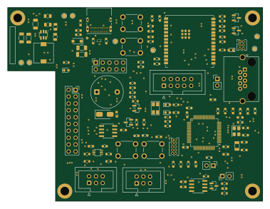 ESP32
IoT Logger B
94.7 × 71.8 mm135 parts2LNo license0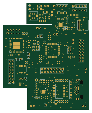 STM32
STM Board
74.1 × 91.8 mm127 parts4LNo license0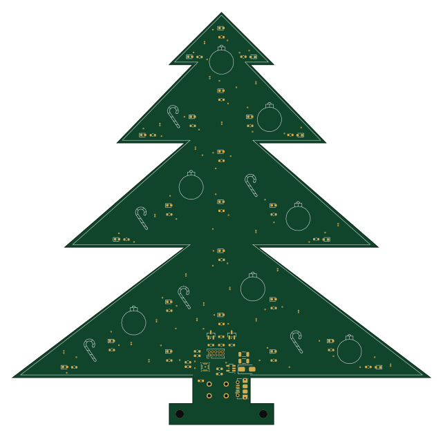 STM32
Tree Board
160 × 158 mm117 parts2LNo license0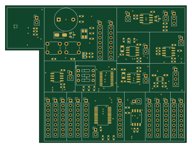
Device Board
94.7 × 71.8 mm104 parts2LNo license0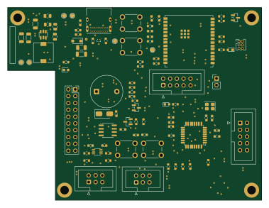 ESP32
IoT Logger C
94.7 × 71.8 mm97 parts2LNo license0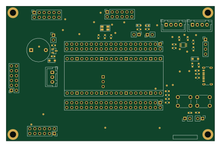 RP2040/RP2350
Main Board
107.5 × 69.8 mm51 parts2LNo license0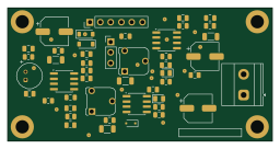
Amplifier Board
64 × 32.1 mm46 parts2LNo license0 RP2040/RP2350
Raspberry Pi Pico Logger
51.5 × 83 mm33 parts2LNo license0 AVR/Arduino
ATMega Board
71.7 × 50.2 mm24 parts2LNo license0 AVR/Arduino
ATMegaSMD Board
71.7 × 50.2 mm24 parts2LNo license0
GPIO Board
64.2 × 35.6 mm21 parts2LNo license0
Similar boards
 Raspberry Pi
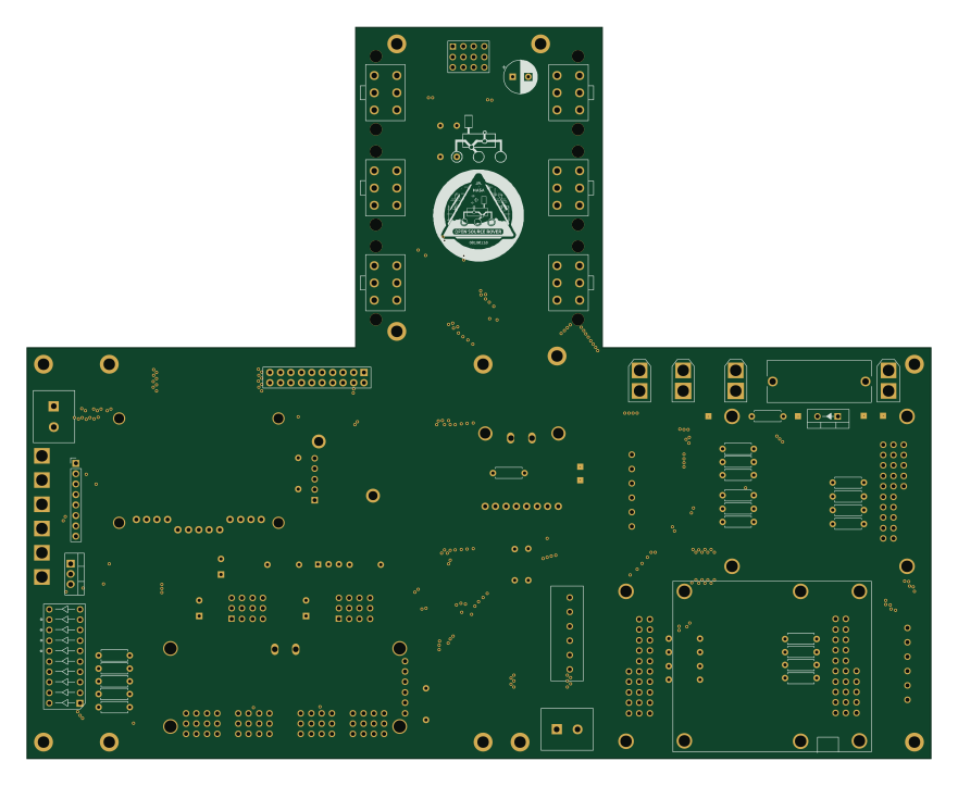
Open source rover
nasa-jpl
220 × 178 mm144 parts2LApache-2.09.7k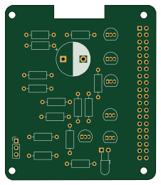 Raspberry Pi
Iot
dotnet
56 × 65 mm24 parts2LMIT2.4k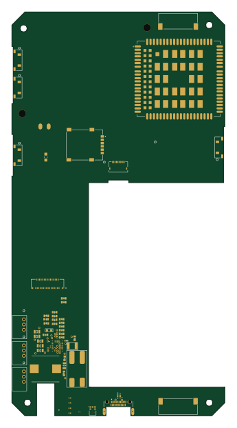 Raspberry Pi
SPIRIT
SPIRIT-org
82 × 155 mm130 parts6LCERN-OHL-S-2.01.3k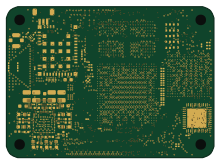 Raspberry Pi
CM5RevEng
schlae
55 × 40 mm417 parts10LNo license1.0k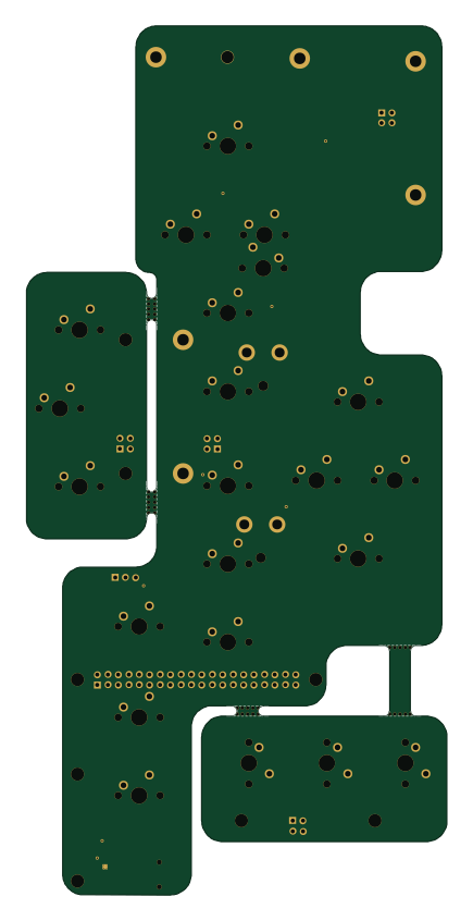 Raspberry Pi
Haxo hw
cardonabits
102.4 × 211.3 mm38 parts2LCustom license673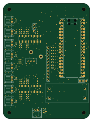 Raspberry Pi
Phased
Neumi
75 × 100 mm71 parts2LNo license507