
Bms test circuit

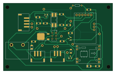
About the Bms test circuit PCB
Bms test circuit is an open source AVR/Arduino PCB design by Wierdwizard2587, published on GitHub. It is a 2-layer board measuring 94.5 × 58.4 mm, with 27 components from 23 distinct parts.
Its main chip is the ATTiny 85 Module, from the AVR/Arduino family. Other key parts include the AOD409, PC817 and MP1584. By type, the board carries 12 resistors, 4 ICs, 4 connectors, 3 transistors, 2 diodes and 1 switch.
It belongs with the audio, power & battery and displays & leds designs in this gallery.
From the project
This is the repository for the Research and Development, Production, and assembly of the Electric Guitar MK1.
- DIY portable electric guitar with integrated digital effects and modular power/audio system - Final version features Teensy 4.0, onboard FX, rotary encoder UI, OLED display, amp/speaker output, battery or DC power, and RGB lighting - Entire build: woodwork, PCBs, 3D prints, firmware, and more - Early prototype (Mk0) failed due to poor electrical design and overcomplex hardware, rebuilt from scratch over 12+ months with newly acquired engineering and fabrication skills
Main components on the Bms test circuit
Bms test circuit bill of materials (BOM)
27 components, 23 distinct parts — part numbers from the project's BOM.
| Qty | Part | Footprint | Refs |
|---|---|---|---|
| 1 | ATTiny 85 Module | Digispark attiny85 board | U1 |
| 1 | AOD409 | TO-252-2 | U3 |
| 1 | PC817 | DIP-4_W8.89mm_SMDSocket_LongPads | U5 |
| 1 | MP1584 | SRT_MPT1584EN_Module | U6 |
| 1 | AO3407 | SOT-23 | Q1 |
| 1 | PN100 | SOT-23 | Q2 |
| 1 | AO3400A | SOT-23 | Q3 |
| 1 | B CHG IN | kf1000 screw terminal | J1 |
| 1 | load chg in | XH 2.54mm 3p smd vertical header | J2 |
| 1 | PWR LOAD OUT | XH 2.54mm 4p vertical header | J3 |
| 1 | Fake Battery input | XH 2.54mm 3p smd vertical header | J4 |
| 1 | SW_DPDT_x2 | SW_CuK_JS202011CQN_DPDT_Straight | SW1 |
| 1 | Thermistor | R_Axial_DIN0204_L3.6mm_D1.6mm_P7.62mm_Horizontal | TH1 |
| 1 | CHG LED | LED_1206_3216Metric | D1 |
| 1 | ON LED | LED_1206_3216Metric | D3 |
| 5 | 10K | R_1206_3216Metric | R1, R5, R11, R13, R15 |
| 1 | 3k3 | R_1206_3216Metric | R4 |
| 1 | 800R | R_1206_3216Metric | R6 |
| 1 | 3K6 | R_1206_3216Metric | R8 |
| 1 | 100K | R_1206_3216Metric | R10 |
Show 3 more
| Qty | Part | Footprint | Refs |
|---|---|---|---|
| 1 | 1.2K | R_1206_3216Metric | R12 |
| 1 | 430R | R_1206_3216Metric | R14 |
| 1 | 330R | R_1206_3216Metric | R16 |
Bms test circuit design files
The KiCad project lives in the Wierdwizard2587/ElectricGuitarMK1 repository on GitHub; these links point at the commit this page was built from.
- LayoutResearch and Development/BMS/PCB Design/3.0 BMS/V3.2/test bms circuit/bms test circuit/bms test circuit.kicad_pcb
- SchematicResearch and Development/BMS/PCB Design/3.0 BMS/V3.2/test bms circuit/bms test circuit/bms test circuit.kicad_sch
- BOMResearch and Development/Interface Section/AFPI/AFPI Final Release Manufacturing Files/PCB Manuafacturing and Assembly/AFPI Device V1.1 BOM.csv
Bms test circuit: common questions
What microcontroller does the Bms test circuit use?
The Bms test circuit is built around the ATTiny 85 Module, from the AVR/Arduino family.
How big is the Bms test circuit PCB?
The Bms test circuit measures 94.5 × 58.4 mm, has 2 copper layers and is 1.6 mm thick.
How many components are on the Bms test circuit?
27 components, from 23 distinct parts, with part numbers taken from the project's own BOM. The full bill of materials is listed on this page.
Where can I download the Bms test circuit design files?
From the Wierdwizard2587/ElectricGuitarMK1 repository on GitHub, which has the KiCad layout, the schematic and the BOM; the links under Design files point to each one.
Can I use the Bms test circuit design in my own project?
The repository has no license, so all rights stay with Wierdwizard2587. Use it as a reference, and ask the author before reusing the design.
Can I test firmware for the Bms test circuit without the hardware?
Yes. HardLabs builds a simulation of the board from its netlist and BOM, so you can run and debug AVR/Arduino firmware against it before you order a PCB.
More boards in ElectricGuitarMK1

BMS
179 × 44 mm64 parts2LNo license1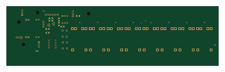 AVR/Arduino
BMS MK2 attempt 1-using-Tp4506
226.6 × 64 mm42 parts2LNo license1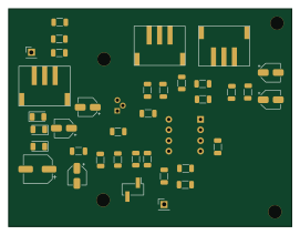
ProCo Rat
67.7 × 52.1 mm38 parts2LNo license1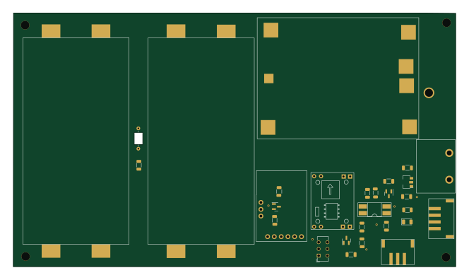 AVR/Arduino
4s2p 18650 Mount, BMS with Power Distribution Circuit
165.7 × 94.8 mm36 parts2LNo license1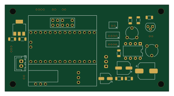 NXP
NXPAFPI Device V1.1
85 × 45 mm28 parts2LNo license1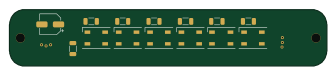
RGB LED Mounting Board
84 × 15 mm16 parts2LNo license1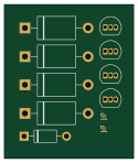
Big muff portion
31 × 37 mm11 parts2LNo license1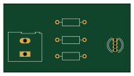
Cnc mill pcb tester
47 × 25.4 mm7 parts2LNo license1
Similar boards
 AVR/Arduino
ModuleV450
stuartpittaway
30 × 61.4 mm39 parts2LCC-BY-NC-4.01.1k AVR/Arduino
V4
30 × 50 mm38 parts2LCC-BY-NC-4.01.1k AVR/Arduino
Easyduino Atmega
Hanqaqa
68.8 × 53.6 mm35 parts4LCERN-OHL-P-2.0746 AVR/Arduino
Easyduino Atmega Nano
43.4 × 18 mm30 parts4LCERN-OHL-P-2.0746 AVR/Arduino
UsbGpib
xyphro
54 × 15 mm21 parts2LMIT683 AVR/Arduino
Lumberjack
peej
284.7 × 94.2 mm149 parts2LMIT402