
RC-Transmitter

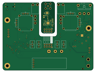
About the RC-Transmitter PCB
RC-Transmitter is an open source RP2040/RP2350 PCB design by Yarnemeuris, published on GitHub. It is a 4-layer board measuring 100 × 75 mm, with 83 components from 53 distinct parts.
Its main chip is the RP2040, from the RP2040/RP2350 family. Other key parts include the MAX17261XXTD, AMS1117-3.3, BQ25887RGE, W25Q128JVS and nRF24L01P. By type, the board carries 32 capacitors, 20 resistors, 9 ICs, 7 switches, 6 connectors and 4 inductors.
It belongs with the power & battery designs in this gallery.
From the project
This is an RC Transmitter for controlling things like planes or cars. It's made with a rp2040 microcontroller and a nRf24 ic for the wireless comunication.
This is an RC Transmitter for controlling things like planes or cars. It's made with a rp2040 microcontroller and a nRf24 ic for the wireless comunication.
The other one is 4 layers and has everything else on it: the input, microcontroller, battery management.
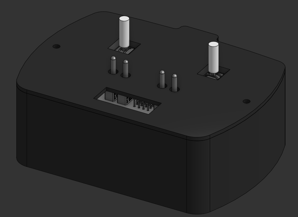
Main components on the RC-Transmitter
RC-Transmitter bill of materials (BOM)
83 components, 53 distinct parts — part numbers from the project's BOM.
| Qty | Part | Footprint | Refs |
|---|---|---|---|
| 1 | MAX17261XXTD MAX17261xxTD | TDFN-14-1EP_3x3mm_P0.4mm_EP1.78x2.35mm | U1 |
| 1 | AMS1117-3.3 | SOT-223-3_TabPin2 | U2 |
| 1 | BQ25887RGE | Texas_RGE0024H_VQFN-24-1EP_4x4mm_P0.5mm_EP2.7x2.7mm_ThermalVias | U3 |
| 1 | W25Q128JVS | SOIC-8_5.3x5.3mm_P1.27mm | U4 |
| 1 | RP2040 | QFN-56-1EP_7x7mm_P0.4mm_EP3.2x3.2mm | U5 |
| 1 | nRF24L01P | QFN-20-1EP_4x4mm_P0.5mm_EP2.5x2.5mm | U6 |
| 1 | RFX2401C | QFN-16_L3.0-W3.0-P0.50-BL-EP1.7 | U7 |
| 1 | C37323741 YF16-DFL7.2-B5KO(45-10)B5KO(55)-RG-A22 | JOYTICK-TH_YF16-DFL7.2-B5KO-45-10-B5KO-55--RG-A22 | U8 |
| 1 | C37323739 YF16-FL7.2-B5KA(45-10)-R-A28 | JOYTICK-TH_YF16-DFL7.2-B5KO-45-10-B5KO-55--RG-A22 | U9 |
| 1 | 12MHZ 12MHz | Crystal_SMD_3225-4Pin_3.2x2.5mm | Y1 |
| 1 | 16MHz | Crystal_Round_D3.0mm_Vertical | Y2 |
| 1 | XT60PW-F_C428722 | TH_2P-XT60PW-F | J1 |
| 1 | HX25418-3WA | CONN-TH_HX25418-3WA | J2 |
| 1 | CONN_01X04 Conn_01x04 | PinHeader_1x04_P2.54mm_Vertical | J3 |
| 1 | BWSMA-KWE-Z001 | SMA-TH_BWSMA-KWE-Z001 | J4 |
| 1 | Conn_02x04_Odd_Even | PinHeader_2x04_P2.54mm_Horizontal | J5 |
| 1 | CONN_02X04_ODD_EVEN Conn_02x04_Odd_Even | PinSocket_2x04_P2.54mm_Horizontal | J6 |
| 1 | Antenna | SolderJumper-2_P1.3mm_Bridged2Bar_Pad1.0x1.5mm | AE1 |
| 1 | SS-12D11G5R | SW-TH_SS-12D11G5R | SW1 |
| 2 | MT-0-102-C004-N004-RS | SW-TH_MT-0-102-C004-N004-RS | SW4, SW5 |
Show 33 more
| Qty | Part | Footprint | Refs |
|---|---|---|---|
| 4 | 2AS3T1A1M2QES | SW-TH_2AS3T1A1M2QES | SW6, SW7, SW8, SW9 |
| 1 | GT-USB-7070A01 | USB-SMD_GT-USB-7070A01 | USB1 |
| 1 | HS91L02W2C01 | OLED-TH_L38.0-W12.0_HS91L02W2C01 | OLED1 |
| 1 | C531288 1µH | L_0402_1005Metric_Pad0.77x0.64mm_HandSolder | L1 |
| 1 | 8.2nH | L_0402_1005Metric_Pad0.77x0.64mm_HandSolder | L2 |
| 1 | 2.7nH | L_0402_1005Metric_Pad0.77x0.64mm_HandSolder | L3 |
| 1 | 3.9nH | L_0402_1005Metric_Pad0.77x0.64mm_HandSolder | L4 |
| 3 | C15850 10µF | C_0805_2012Metric | C1, C3, C7 |
| 11 | 100NF 100nF | C_0402_1005Metric_Pad0.74x0.62mm_HandSolder | C2, C8, C11, C12, C14, C15, C17, C18 +3 |
| 1 | C76659 44µF | C_1206_3216Metric_Pad1.33x1.80mm_HandSolder | C4 |
| 1 | 47NF 47nF | C_0402_1005Metric_Pad0.74x0.62mm_HandSolder | C5 |
| 1 | C23733 4.7µF | C_0402_1005Metric_Pad0.74x0.62mm_HandSolder | C6 |
| 2 | 22PF 22pF | C_0402_1005Metric_Pad0.74x0.62mm_HandSolder | C9, C10 |
| 2 | C14445 1µF | C_0402_1005Metric_Pad0.74x0.62mm_HandSolder | C13, C16 |
| 1 | 1nF | C_0402_1005Metric_Pad0.74x0.62mm_HandSolder | C21 |
| 1 | 33nF | C_0402_1005Metric_Pad0.74x0.62mm_HandSolder | C22 |
| 1 | 10nF | C_0402_1005Metric_Pad0.74x0.62mm_HandSolder | C23 |
| 1 | 100nF | C_0402_1005Metric_Pad0.74x0.62mm_HandSolder | C24 |
| 1 | 10µF | C_0805_2012Metric | C25 |
| 1 | 2.2nF | C_0402_1005Metric_Pad0.74x0.62mm_HandSolder | C26 |
| 2 | 22pF | C_0402_1005Metric_Pad0.74x0.62mm_HandSolder | C27, C28 |
| 1 | 4.7pF | C_0402_1005Metric_Pad0.74x0.62mm_HandSolder | C29 |
| 1 | 1.5pF | C_0402_1005Metric_Pad0.74x0.62mm_HandSolder | C30 |
| 1 | 1pF | C_0402_1005Metric_Pad0.74x0.62mm_HandSolder | C31 |
| 6 | 5.1kΩ | R_0402_1005Metric_Pad0.72x0.64mm_HandSolder | R1, R5, R16, R17, R18, R19 |
| 1 | 200KΩ | R_0402_1005Metric_Pad0.72x0.64mm_HandSolder | R2 |
| 1 | 10mΩ | R_1206_3216Metric_Pad1.30x1.75mm_HandSolder | R3 |
| 1 | 1.3MΩ | R_0402_1005Metric_Pad0.72x0.64mm_HandSolder | R4 |
| 5 | 10KΩ | R_0402_1005Metric_Pad0.72x0.64mm_HandSolder | R6, R7, R8, R10, R20 |
| 1 | 300Ω | R_1206_3216Metric_Pad1.30x1.75mm_HandSolder | R9 |
| 2 | 1kΩ | R_0402_1005Metric_Pad0.72x0.64mm_HandSolder | R11, R14 |
| 2 | 27Ω | R_0402_1005Metric_Pad0.72x0.64mm_HandSolder | R12, R13 |
| 1 | 22kΩ | R_0402_1005Metric_Pad0.72x0.64mm_HandSolder | R15 |
RC-Transmitter design files
The KiCad project lives in the Yarnemeuris/RC-Transmitter repository on GitHub; these links point at the commit this page was built from.
RC-Transmitter: common questions
What microcontroller does the RC-Transmitter use?
The RC-Transmitter is built around the RP2040, from the RP2040/RP2350 family.
How big is the RC-Transmitter PCB?
The RC-Transmitter measures 100 × 75 mm, has 4 copper layers and is 1.6 mm thick.
How many components are on the RC-Transmitter?
83 components, from 53 distinct parts, with part numbers taken from the project's own BOM. The full bill of materials is listed on this page.
Where can I download the RC-Transmitter design files?
From the Yarnemeuris/RC-Transmitter repository on GitHub, which has the KiCad layout, the schematic and the BOM; the links under Design files point to each one.
Can I use the RC-Transmitter design in my own project?
The repository has no license, so all rights stay with Yarnemeuris. Use it as a reference, and ask the author before reusing the design.
Can I test firmware for the RC-Transmitter without the hardware?
Yes. HardLabs builds a simulation of the board from its netlist and BOM, so you can run and debug RP2040/RP2350 firmware against it before you order a PCB.
Similar boards
 RP2040/RP2350
OSO-BOOK-C1
joeycastillo
85 × 115 mm29 parts2LCC-BY-SA-4.08.1k RP2040/RP2350
Corne cherry
foostan
277.2 × 107.5 mm164 parts2LCC-BY-4.07.7k RP2040/RP2350
Corne chocolate
277.2 × 107.5 mm164 parts2LCC-BY-4.07.7k RP2040/RP2350
Jitx design
gusmanb
55.5 × 65 mm26 parts4LGPL-3.05.0k RP2040/RP2350
LogicAnalyzer
57 × 55.2 mm6 parts2LGPL-3.05.0k RP2040/RP2350
Main
google
98 × 71 mm102 parts2LApache-2.02.9k