
Powermod

About the Powermod PCB
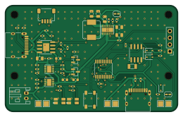
Powermod is an open source PCB design by zdeager, published on GitHub. It is a 4-layer board measuring 65 × 40 mm, with 65 components from 34 distinct parts.
Other key parts include the BM8563ESA, PY32F003F18P6, TPS63020DSJR, TP4056 and XC6206P332MR. By type, the board carries 28 resistors, 16 capacitors, 5 ICs, 5 connectors, 5 diodes and 3 transistors.
It belongs with the power & battery designs in this gallery.
From the project
Machine-generated PCB design for a Raspberry Pi Zero 2 W power scheduler / UPS / battery board. The electrical design is defined in code (netlist.py); the board was laid out and routed with the scripted KiCad + Freerouting toolchain below, then hand-finished.
Machine-generated PCB design for a Raspberry Pi Zero 2 W power scheduler / UPS / battery board. The electrical design is defined in code (netlist.py); the board was laid out and routed with the scripted KiCad + Freerouting toolchain below, then hand-finished.
65 × 40 mm, 4-layer (F.Cu signal / In1 solid GND / In2 signal / B.Cu signal). Bolts under a Pi Zero 2 W (holes on the Pi's 58×23 grid, flush to the N+W edges); the Pi covers y0–30, and all user-facing parts (USB-C out, battery, button, LEDs, jumpers, test pads) sit on the exposed strip below it. Single-sided assembly.
Main components on the Powermod
Powermod bill of materials (BOM)
65 components, 34 distinct parts — part numbers from the project's BOM.
| Qty | Part | Footprint | Refs |
|---|---|---|---|
| 1 | BM8563ESA BM8563 | SOIC-8_3.9x4.9mm_P1.27mm | U1 |
| 1 | PY32F003F18P6 | TSSOP-20_4.4x6.5mm_P0.65mm | U2 |
| 1 | TPS63020DSJR | VSON-14-1EP_3x4.45mm_P0.65mm_EP1.6x4.2mm | U3 |
| 1 | TP4056 | SOIC-8-1EP_3.9x4.9mm_P1.27mm_EP2.29x3mm | U4 |
| 1 | XC6206P332MR | SOT-23 | U5 |
| 2 | AON7407 | DFN-8-1EP_3x3mm_P0.65mm_EP1.6x2.56mm | Q1, Q2 |
| 1 | BSS138 | SOT-23 | Q3 |
| 1 | Q13FC13500004 32.768kHz | Crystal_SMD_3215-2Pin_3.2x1.5mm | Y1 |
| 1 | C165948 USB_C_IN | USB_C_Receptacle_TYPE-C_16P_PowerMerged | J1 |
| 1 | C165948 USB_C_OUT | USB_C_Receptacle_TYPE-C_16P_PowerMerged | J2 |
| 1 | JST_PH_2 | JST_PH_S2B-PH-K_1x02_P2.00mm_Horizontal | J3 |
| 1 | C51940130 STEMMA_QT | JST_SH_SM04B-SRSS-TB_1x04-1MP_P1.00mm_Horizontal | J4 |
| 1 | SWD_HDR | PinHeader_1x04_P2.54mm_Vertical | J5 |
| 1 | C2799414 BUTTON | SW_SPST_PTS647_Sx50 | SW1 |
| 2 | TJ-S3227 | LED_TJ-S3227_RG_3.2x2.7mm | D1, D2 |
| 3 | 1N4148WS | D_SOD-323 | D3, D4, D5 |
| 1 | 1.5UH 1.5uH_4.5A | L_Sumida_CDMC6D28_7.25x6.5mm | L1 |
| 3 | 10U 10u | C_0805_2012Metric | C1, C2, C7 |
| 3 | 22U 22u | C_0805_2012Metric | C3, C4, C5 |
| 1 | 4.7U 4.7u | C_0603_1608Metric | C6 |
Show 14 more
| Qty | Part | Footprint | Refs |
|---|---|---|---|
| 2 | 1u | C_0603_1608Metric | C8, C9 |
| 7 | 100N 100n | C_0402_1005Metric | C10, C11, C12, C13, C14, C15, C16 |
| 1 | 1.2K 1.2k | R_0402_1005Metric | R1 |
| 2 | 5.1K 5.1k | R_0402_1005Metric | R2, R3 |
| 2 | 56K 56k | R_0402_1005Metric | R4, R5 |
| 3 | 1M | R_0402_1005Metric | R6, R8, R25 |
| 2 | 330K 330k | R_0402_1005Metric | R7, R9 |
| 5 | 100K 100k | R_0402_1005Metric | R10, R12, R13, R14, R28 |
| 1 | 47K 47k | R_0402_1005Metric | R11 |
| 5 | 10K 10k | R_0402_1005Metric | R15, R16, R17, R18, R19 |
| 4 | 560 | R_0402_1005Metric | R20, R21, R22, R23 |
| 1 | 180K 180k | R_0402_1005Metric | R24 |
| 1 | 620K 620k | R_0402_1005Metric | R26 |
| 1 | 1k | R_0402_1005Metric | R27 |
Powermod design files
The KiCad project lives in the zdeager/powermod repository on GitHub; these links point at the commit this page was built from.
Powermod: common questions
How big is the Powermod PCB?
The Powermod measures 65 × 40 mm, has 4 copper layers and is 1.6 mm thick.
How many components are on the Powermod?
65 components, from 34 distinct parts, with part numbers taken from the project's own BOM. The full bill of materials is listed on this page.
Where can I download the Powermod design files?
From the zdeager/powermod repository on GitHub, which has the KiCad layout, the schematic and the BOM; the links under Design files point to each one.
Can I use the Powermod design in my own project?
The repository has no license, so all rights stay with zdeager. Use it as a reference, and ask the author before reusing the design.
Similar boards

Stack chan
stack-chan
50 × 50 mm33 parts2LApache-2.01.7k
Display Carrier
AxxAxx
35.6 × 58.2 mm5 parts2LGPL-3.01.7k
ControllerCurrentShuntAddOn
stuartpittaway
26 × 16.9 mm9 parts2LCC-BY-NC-4.01.1k
Module 16S PassiveBalanceAddOn
61 × 74 mm86 parts2LCC-BY-NC-4.01.1k
TemperaturePCB PANEL
116 × 75.5 mm178 parts2LCC-BY-NC-4.01.1k
ProgrammingAdapter
10.5 × 83 mm3 parts2LCC-BY-NC-4.01.1k