
40 open source boards using the TPS63020DSJR
Real designs built with the TPS63020DSJR, from public GitHub projects: a quick way to see how others power, decouple and connect it. Each board comes with its KiCad files, full parts list and a render — and you can simulate its firmware on HardLabs.
 ESP32
Badge
atopile
56.3 × 39 mm239 parts4LMIT4.0k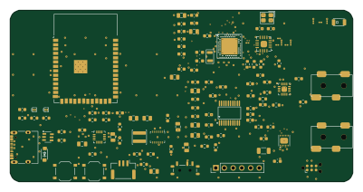 ESP32
Open motorcycle intercom
d3vv3
100 × 50 mm116 parts4LMIT68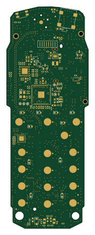
Sisu SSE-9
briskspirit
43.9 × 118.2 mm259 parts6LUnlicense18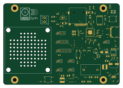 RP2040/RP2350
HDD Synth Prototype MK5
MaverickUK
100.3 × 69.9 mm101 parts2LCC-BY-NC-4.015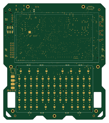 ESP32
Tanmatsu hardware
Nicolai-Electronics
114.9 × 129.9 mm320 parts4LCERN-OHL-P-2.09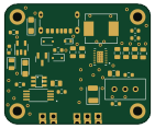
Bms buck boost
tor1kk
35.1 × 28.9 mm34 parts2LGPL-3.09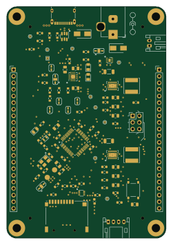 STM32
Bluegrass
agrif
61 × 88.9 mm107 parts4LCC-BY-SA-4.02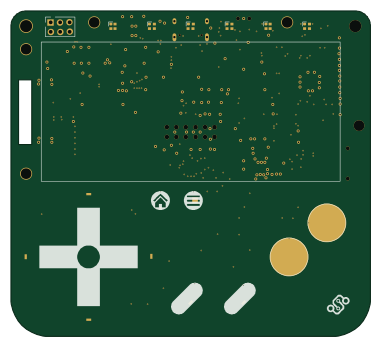 ESP32
Kami hardware
95 × 86 mm100 parts4LCERN-OHL-P-2.02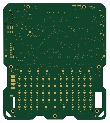 ESP32
Why2025
ranzbak
114.9 × 129.9 mm327 parts4LNo license1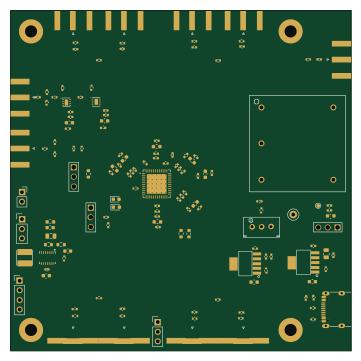 STM32
CLOCK
Han-ZenX
90 × 90 mm157 parts4LCustom license1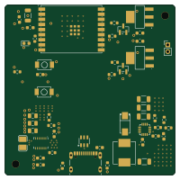 ESP32
Electropulse
Shehroz30
50 × 50 mm51 parts4LMIT1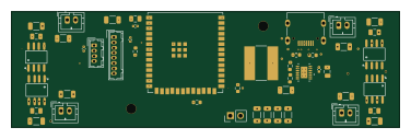 ESP32
Lux
Erox-02
94 × 28 mm46 parts4LGPL-3.01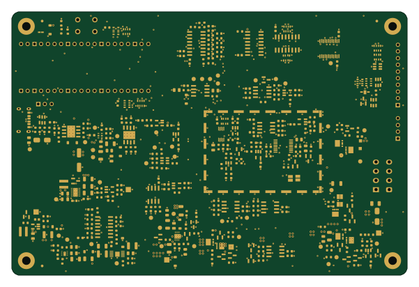 RP2040/RP2350
Open power profiler
Guiimartinho
150 × 100 mm365 parts4LMIT0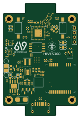 ESP32
Beehive-Monitoring
GhanmiIyed
40.1 × 60.5 mm85 parts4LNo license0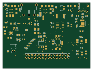
EEE3088F-MicroMouse-Power-Board-Group-21
MikeLight11
80 × 60 mm78 parts2LNo license0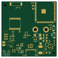 ESP32
Wireslesslock
50 × 50 mm67 parts4LMIT0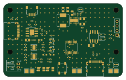
Powermod
zdeager
65 × 40 mm65 parts4LNo license0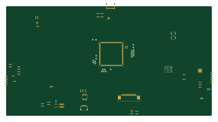 ESP32
DesignSpecialProject5
StefVuck
211.9 × 113.2 mm60 parts4LNo license0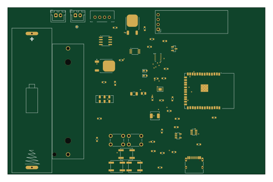 ESP32
Battery monitor
kaushalch1
134.5 × 87 mm55 parts2LNo license0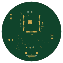 ESP32
Hush main
Terryzhao-dev
64 × 64 mm52 parts4LNo license0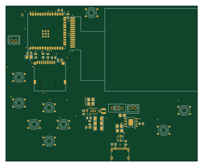 ESP32
Esp-32-gaming console
lewipewi
99 × 80 mm51 parts4LNo license0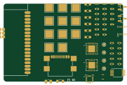 ESP32
Daronjli dongle
manhoosbilli1
45.2 × 29.7 mm50 parts4LNo license0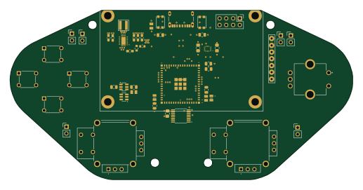 ESP32
HexControllerV3
TH4R4V3N1324
129 × 63.9 mm49 parts4LNo license0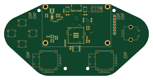 ESP32
HexControllerV3
129 × 63.9 mm49 parts4LNo license0 ESP32
Phyto pulse
jayis1
80 × 50 mm37 parts4LNo license0 RP2040/RP2350
Solardeck
lorecrafting
222 × 160 mm36 parts6LCustom license0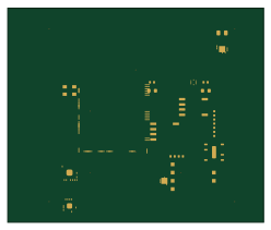 STM32
TideBand — Wrist-Worn Hydrographic Current Profiler
62 × 52 mm24 parts5LNo license0- schematic only · 64 partsESP32
Pocket ebook reader
niyoseris
64 partsMIT0 - schematic only · 29 partsESP32
Proto harness
Okohedeki
29 partsMIT0 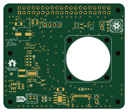
Pi hat ups
Doenec
65 × 56 mm62 parts4LMIT1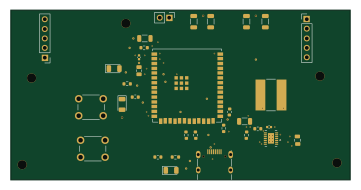 ESP32
Remote
90 × 45 mm33 parts4LGPL-3.01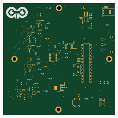 AVR/Arduino
Chessconnect uP
K-0hm
100 × 100 mm88 parts2LGPL-3.00 ESP32
Opti rot
160 × 65 mm34 parts2LNo license0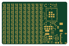 ESP32
Badge
glovepost
59.3 × 39 mm245 parts4LMIT1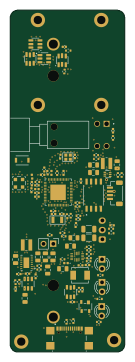 ESP32
Base station
Tinkerbug-Robotics
30.3 × 90.5 mm109 parts4LGPL-3.00 ESP32
QCM Halo — Pocket QCM-D Instrument
90 × 60 mm27 parts4LNo license0
How designs wire the TPS63020DSJR
Read from the KiCad layouts of 30 open source designs, one per repository: what each pin of the TPS63020DSJR connects to, and the resistors, capacitors and other passives placed on it.
- The L2_6 pin has a inductor on 28 of 29 designs, most often 1.5 µH (then 2.2 µH).
- The L2_7 pin has a inductor on 28 of 30 designs, most often 1.5 µH (then 2.2 µH).
- The L1_9 pin has a inductor on 28 of 30 designs, most often 1.5 µH (then 2.2 µH).
- The L1_8 pin has a inductor on 27 of 29 designs, most often 1.5 µH (then 2.2 µH).
| Pin | Connected to | Parts on the pin |
|---|---|---|
| VINApin 1 | Connected to: Signal 66% · VSYS 34% |
|
| GNDpin 2 | Connected to: GND 97% | — |
| FBpin 3 | Connected to: Signal 97% |
|
| VOUT_4pin 4 | Connected to: 3.3V 77% · a signal 23% |
|
| VOUT_5pin 5 | Connected to: 3.3V 76% · a signal 24% |
|
| L2_6pin 6 | Connected to: Signal 97% |
|
| L2_7pin 7 | Connected to: Signal 93% |
|
| L1_8pin 8 | Connected to: Signal 93% |
|
| L1_9pin 9 | Connected to: Signal 90% |
|
| VIN_10pin 10 | Connected to: VSYS 73% · a signal 27% |
|
| VIN_11pin 11 | Connected to: VSYS 73% · a signal 27% |
|
| ENpin 12 | Connected to: Signal 72% · VSYS 28% |
|
| PS/SYNCpin 13 | Connected to: Signal 52% · GND 38% |
|
| PGpin 14 | Connected to: Not connected 69% · a signal 31% | — |
| PGND_15pin 15 | Connected to: GND 100% | — |
Connections count pins, parts count designs; values in brackets are how many parts had that value. Designs read include Badge by atopile, Open motorcycle intercom by d3vv3, Sisu SSE-9 by briskspirit and HDD Synth Prototype MK5 by MaverickUK.
The TPS63020DSJR in open source designs
The gallery holds 40 open source boards using the TPS63020DSJR from 34 GitHub repositories; a typical one measures about 85 × 63.8 mm and carries around 63 components.
84% use four copper layers or more, and 48% carry an open source license.
The most starred is Badge by atopile.
Parts used alongside the TPS63020DSJR
Microcontrollers on boards using the TPS63020DSJR
What boards using the TPS63020DSJR are built for
TPS63020DSJR: common questions
Where can I find a TPS63020DSJR reference design?
Each of the 40 boards on this page is a real design using the TPS63020DSJR. Open one to see how it is wired up, with the full BOM, a render of the layout and links to its KiCad files.
How is the TPS63020DSJR L2_6 pin connected?
The L2_6 pin has a inductor on 28 of 29 designs, most often 1.5 µH (then 2.2 µH). Counted from the KiCad layouts of 30 open source designs using the TPS63020DSJR.
How is the TPS63020DSJR L2_7 pin connected?
The L2_7 pin has a inductor on 28 of 30 designs, most often 1.5 µH (then 2.2 µH). Counted from the KiCad layouts of 30 open source designs using the TPS63020DSJR.
How is the TPS63020DSJR L1_9 pin connected?
The L1_9 pin has a inductor on 28 of 30 designs, most often 1.5 µH (then 2.2 µH). Counted from the KiCad layouts of 30 open source designs using the TPS63020DSJR.
What parts are used alongside the TPS63020DSJR?
The USBLC6-2SC6, DW01A, TP4056, ESP32-C3-MINI-1-N4 and W25Q128JVS appear in the most repositories here.
Which microcontrollers do boards using the TPS63020DSJR use?
Most are built on ESP32 (28), RP2040/RP2350 (3), STM32 (3) and AVR/Arduino (1).
How big is a typical board using the TPS63020DSJR?
The median is 85 × 63.8 mm, and 16% are two-layer designs.
What is the most popular open source board using the TPS63020DSJR?
By GitHub stars, Badge by atopile, with 4,032 stars.
Can I simulate one of these boards using the TPS63020DSJR before building it?
Yes. HardLabs turns a board's netlist and BOM into a working simulation, so you can boot and test firmware against it with no hardware on your desk.