
PLC RestoMod Digital I/O

About the PLC RestoMod Digital I/O PCB
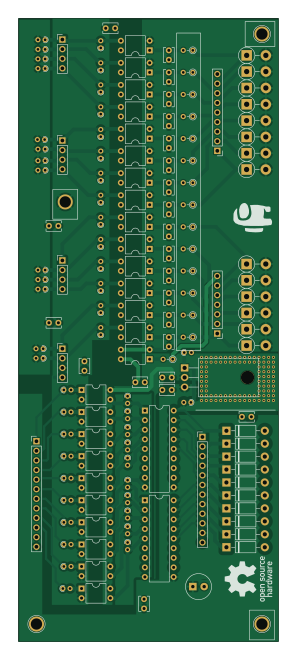
PLC RestoMod Digital I/O is an open source PCB design by akbar-q, published on GitHub. It is a 2-layer board measuring 68.7 × 164.9 mm, with 132 components from 21 distinct parts.
Other key parts include the LM317_SOT-223, PC817, LM337_SOT223 and ULN2803A. By type, the board carries 51 resistors, 28 ICs, 24 diodes, 20 capacitors, 8 connectors and 1 buzzer.
It belongs with the audio and power & battery designs in this gallery.
From the project
This repository showcases a curated selection of my original electronics hardware designs. These projects span power electronics, RF systems, digital logic, and embedded hardware, each built with an emphasis on practical validation, clean design, and production-readiness.
This repository showcases a curated selection of my original electronics hardware designs. These projects span power electronics, RF systems, digital logic, and embedded hardware, each built with an emphasis on practical validation, clean design, and production-readiness.
With over three years of hands-on experience, I specialize in taking ideas from concept to lab-verified prototypes. My approach blends solid engineering principles with detailed testing and manufacturing-aware design. I work across the full lifecycle—from schematic capture and BOM optimization to PCB layout, fabrication…
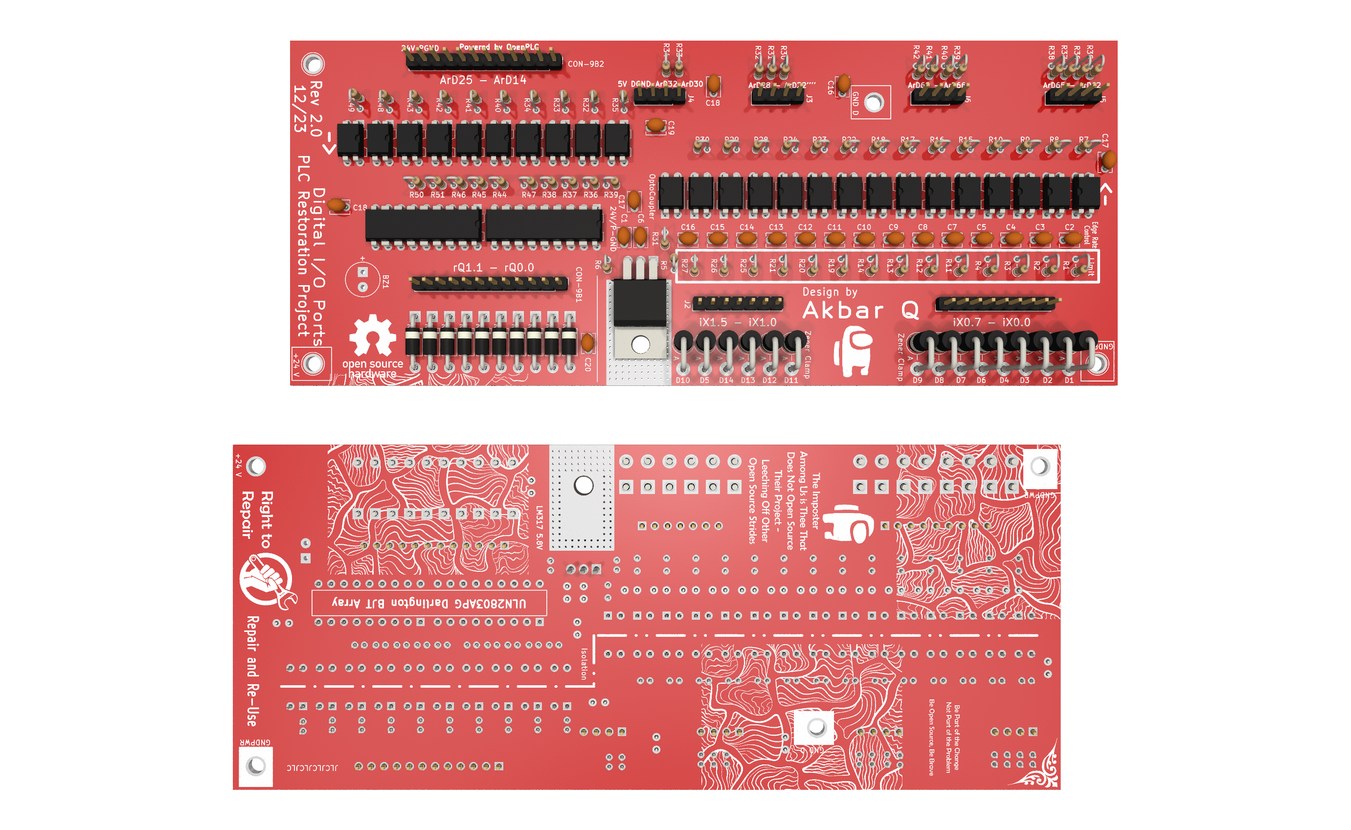
Main components on the PLC RestoMod Digital I/O
PLC RestoMod Digital I/O bill of materials (BOM)
132 components, 21 distinct parts — part numbers from the project's BOM.
| Qty | Part | Footprint | Refs |
|---|---|---|---|
| 1 | LM317_SOT-223 LM317_TO-220 | TO-220-3_Horizontal_TabDown | U1 |
| 24 | PC817 | DIP-4_W7.62mm | U2, U4, U5, U6, U7, U8, U9, U10 +16 |
| 1 | LM337_SOT223 PC817 | DIP-4_W7.62mm | U3 |
| 2 | ULN2803A | DIP-18_W7.62mm | U17, U18 |
| 2 | Conn_01x12_Pin | PinHeader_1x12_P2.54mm_Vertical | CON-9B1, CON-9B2 |
| 1 | Conn_01x09_Male | PinHeader_1x09_P2.54mm_Vertical | J1 |
| 1 | Conn_01x07_Male | PinHeader_1x07_P2.54mm_Vertical | J2 |
| 4 | Conn_01x04_Pin | PinHeader_1x04_P2.54mm_Vertical | J3, J4, J5, J6 |
| 1 | Buzzer | MagneticBuzzer_Kobitone_254-EMB73-RO | BZ1 |
| 14 | D_Zener | D_5W_P5.08mm_Vertical_AnodeUp | D1, D2, D3, D4, D5, D6, D7, D8 +6 |
| 10 | 1N4007 | D_DO-41_SOD81_P10.16mm_Horizontal | D15, D16, D17, D18, D19, D20, D21, D22 +2 |
| 8 | 2.2U C_Small | C_Disc_D3.8mm_W2.6mm_P2.50mm | C1, C2, C3, C4, C6, C7, C8, C9 |
| 2 | 100N C_Small | C_Disc_D3.8mm_W2.6mm_P2.50mm | C5, C10 |
| 10 | C_Small | C_Disc_D3.8mm_W2.6mm_P2.50mm | C11, C12, C13, C14, C15, C16, C17, C18 +2 |
| 8 | 680R 1.2k | R_Axial_DIN0204_L3.6mm_D1.6mm_P2.54mm_Vertical | R1, R2, R3, R4, R11, R12, R13, R14 |
| 1 | 680R 1.2k | R_Axial_DIN0204_L3.6mm_D1.6mm_P1.90mm_Vertical | R5 |
| 1 | 680R 330 | R_Axial_DIN0204_L3.6mm_D1.6mm_P1.90mm_Vertical | R6 |
| 8 | 680R 1k | R_Axial_DIN0204_L3.6mm_D1.6mm_P1.90mm_Vertical | R7, R8, R9, R10, R15, R16, R17, R18 |
| 7 | 1.2k | R_Axial_DIN0204_L3.6mm_D1.6mm_P2.54mm_Vertical | R19, R20, R21, R25, R26, R27, R31 |
| 17 | 1k | R_Axial_DIN0204_L3.6mm_D1.6mm_P1.90mm_Vertical | R22, R23, R24, R28, R29, R30, R36, R37 +9 |
Show 1 more
| Qty | Part | Footprint | Refs |
|---|---|---|---|
| 9 | 220 | R_Axial_DIN0204_L3.6mm_D1.6mm_P1.90mm_Vertical | R32, R33, R34, R35, R40, R42, R43, R48 +1 |
PLC RestoMod Digital I/O design files
The KiCad project lives in the akbar-q/Circuits-PCB-HardwareDesign repository on GitHub; these links point at the commit this page was built from.
PLC RestoMod Digital I/O: common questions
How big is the PLC RestoMod Digital I/O PCB?
The PLC RestoMod Digital I/O measures 68.7 × 164.9 mm, has 2 copper layers and is 1.6 mm thick.
How many components are on the PLC RestoMod Digital I/O?
132 components, from 21 distinct parts, with part numbers taken from the project's own BOM. The full bill of materials is listed on this page.
Where can I download the PLC RestoMod Digital I/O design files?
From the akbar-q/Circuits-PCB-HardwareDesign repository on GitHub, which has the KiCad layout, the schematic and the BOM; the links under Design files point to each one.
Can I use the PLC RestoMod Digital I/O design in my own project?
The repository has no license, so all rights stay with akbar-q. Use it as a reference, and ask the author before reusing the design.
More boards in Circuits-PCB-HardwareDesign
 ESP32
MPPT-Controller
99 × 99 mm96 parts4LNo license0 ESP32
020 NiMH Battery Charger
100 × 72.8 mm82 parts2LNo license0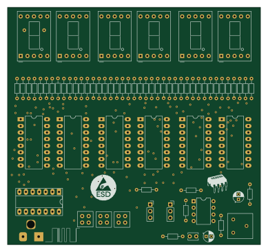
Practise PCB For Clock/Counter
97 × 91 mm67 parts2LNo license0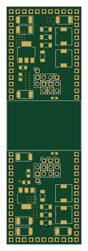
Linear Power Supply for Amplifier
28.6 × 91.2 mm60 parts4LNo license0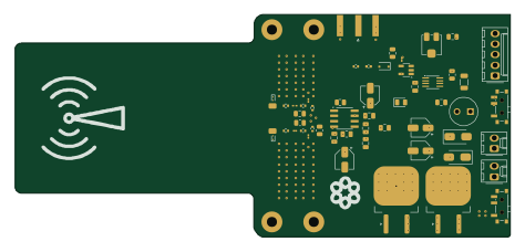
High Voltage Arc Detector
118.2 × 53.2 mm53 parts4LNo license0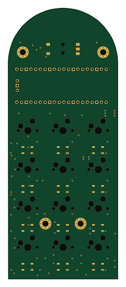 RP2040/RP2350
Macro Keypad w/ Rotary on Top
59.2 × 146.2 mm50 parts2LNo license0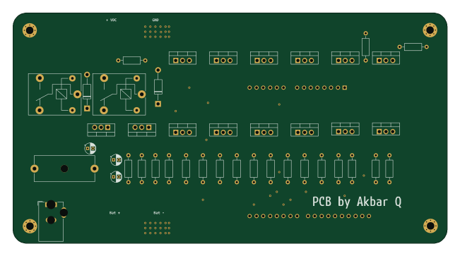 AVR/Arduino
Draft PCB for Potential Partnership for E-Bike Conversion
162.6 × 86.4 mm44 parts2LNo license0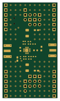
Sub 2 GHz Amplifier
28.6 × 49.5 mm31 parts4LNo license0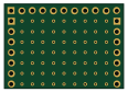
Filter Plate to Cover Power
28.6 × 20.4 mm3 parts2LNo license0
Similar boards
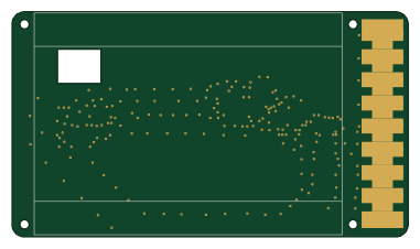
EinkPDA screen
TalismanDesign
95 × 54 mm27 parts2LApache-2.02.0k
Stack chan
stack-chan
50 × 50 mm33 parts2LApache-2.01.7k
Display Carrier
AxxAxx
35.6 × 58.2 mm5 parts2LGPL-3.01.7k
KLOR
GEIGEIGEIST
160.2 × 118.3 mm79 parts2LGPL-3.01.2k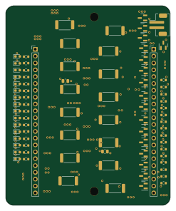
Module 16S PassiveBalanceAddOn
stuartpittaway
61 × 74 mm86 parts2LCC-BY-NC-4.01.1k
TemperaturePCB PANEL
116 × 75.5 mm178 parts2LCC-BY-NC-4.01.1k