
Breakout board v4

About the Breakout board v4
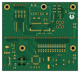
Breakout board v4 is an open source Microchip SAM PCB design by asinghani, published on GitHub. It is a 4-layer board measuring 81.3 × 73.9 mm, with 91 components from 32 distinct parts.
Its main chip is the ATSAMD21G18A-A, from the Microchip SAM family. Other key parts include the caravel-M.2-card, AP2112K-1.8 and AZ1117-3.3. By type, the board carries 31 resistors, 24 capacitors, 16 diodes, 5 ICs, 5 connectors and 5 jumpers.
It belongs with the dev boards & breakouts designs in this gallery, and the repository also holds 3 earlier revisions of it.
From the project
PCB layouts for student project bringup for CMU Open Source Chip Design Spring 2023 tapeout
If you have picked up your kit from ECE, please see BRINGUP.md for instructions on how to get started using it!
If you are interested in the process to assemble the boards/kits, see ASSEMBLY.md
- Breakout Board v1 Schematic - Buttons/Switches Board Schematic - Debugger Board Schematic
Main components on the Breakout board v4
Breakout board v4 bill of materials (BOM)
91 components, 32 distinct parts.
| Qty | Part | Footprint | Refs |
|---|---|---|---|
| 1 | ATSAMD21G18A-A | TQFP-48_7x7mm_P0.5mm | U1 |
| 1 | caravel-M.2-card | M.2-CONNECTOR-E | U2 |
| 1 | AP2112K-1.8 | SOT-23-5 | U3 |
| 1 | DNF | SOIC-8_5.23x5.23mm_P1.27mm | U4 |
| 1 | AZ1117-3.3 | SOT-223-3_TabPin2 | U5 |
| 1 | 32.768KHz | Crystal_SMD_HC49-SD | Y1 |
| 1 | TC2050 | Tag-Connect_TC2050-IDC-FP_2x05_P1.27mm_Vertical | J1 |
| 1 | SMA_CONN | SMB_Jack_Vertical | J2 |
| 1 | BREAKOUT_HDR | PinHeader_1x30_P2.54mm_Vertical | J3 |
| 1 | HKSPI_HDR | PinHeader_1x06_P2.54mm_Vertical | J4 |
| 1 | USB_C_Receptacle_USB2.0 | USB_C_Receptacle_HRO_TYPE-C-31-M-12 | J5 |
| 1 | 500mA | Fuse_1206_3216Metric_Pad1.42x1.75mm_HandSolder | F1 |
| 1 | MICROMOD-Standoff | MicroMod-Standoff | H1 |
| 1 | RST_JMP | PinHeader_1x02_P2.54mm_Vertical | JP1 |
| 1 | VCCD_JMP | SolderJumper-2_P1.3mm_Bridged2Bar_Pad1.0x1.5mm | JP2 |
| 1 | VDDA_JMP | SolderJumper-2_P1.3mm_Bridged2Bar_Pad1.0x1.5mm | JP3 |
| 1 | SOC_RST_JMP | SolderJumper-2_P1.3mm_Bridged2Bar_Pad1.0x1.5mm | JP4 |
| 1 | VDDIO_JMP | SolderJumper-2_P1.3mm_Bridged2Bar_Pad1.0x1.5mm | JP5 |
| 1 | RST_BTN | SW_Push_1P1T_NO_6x6mm_H9.5mm | SW1 |
| 1 | DSHP08TSGER | SW_DIP_SPSTx08_Slide_KingTek_DSHP08TS_W7.62mm_P1.27mm | SW2 |
Show 12 more
| Qty | Part | Footprint | Refs |
|---|---|---|---|
| 1 | 3V3 | LED_0805_2012Metric | D1 |
| 14 | LED | LED_0805_2012Metric | D2, D3, D4, D6, D7, D8, D9, D10 +6 |
| 1 | 1V8 | LED_0805_2012Metric | D5 |
| 2 | 22p | C_0603_1608Metric | C1, C2 |
| 8 | 0.1u | C_0603_1608Metric | C3, C5, C7, C8, C9, C12, C13, C20 |
| 8 | 1u | C_0603_1608Metric | C4, C6, C11, C14, C15, C19, C21, C24 |
| 5 | 10u | C_0603_1608Metric | C10, C16, C18, C22, C23 |
| 1 | DNF | C_0603_1608Metric_Pad1.08x0.95mm_HandSolder | C17 |
| 9 | 10K | R_0805_2012Metric | R1, R2, R3, R4, R5, R6, R7, R8 +1 |
| 5 | DNF | R_0805_2012Metric | R9, R10, R11, R13, R14 |
| 15 | 1K | R_0805_2012Metric | R15, R16, R17, R18, R19, R20, R21, R22 +7 |
| 2 | 5.1K | R_0805_2012Metric | R30, R31 |
Breakout board v4 design files
The KiCad project lives in the asinghani/18224-tapeout-s23-bringup repository on GitHub; these links point at the commit this page was built from.
Breakout board v4: common questions
What microcontroller does the Breakout board v4 use?
The Breakout board v4 is built around the ATSAMD21G18A-A, from the Microchip SAM family.
How big is the Breakout board v4?
The Breakout board v4 measures 81.3 × 73.9 mm, has 4 copper layers and is 1.6 mm thick.
How many components are on the Breakout board v4?
91 components, from 32 distinct parts. The full bill of materials is listed on this page.
Where can I download the Breakout board v4 design files?
From the asinghani/18224-tapeout-s23-bringup repository on GitHub, which has the KiCad layout and the schematic; the links under Design files point to each one.
Can I use the Breakout board v4 design in my own project?
The repository has no license, so all rights stay with asinghani. Use it as a reference, and ask the author before reusing the design.
Can I test firmware for the Breakout board v4 without the hardware?
Yes. HardLabs builds a simulation of the board from its netlist and BOM, so you can run and debug Microchip SAM firmware against it before you order a PCB.
More boards in 18224-tapeout-s23-bringup
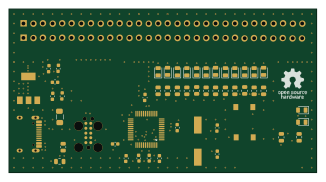
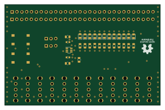

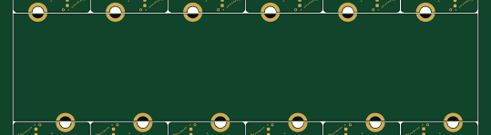
Earlier revisions in the repo: breakout_board_v3, breakout_board_v2, breakout_board_v1
Similar boards
 Microchip SAM
Microcontroller Expansion Card
FrameworkComputer
26 × 30 mm24 parts2LCC-BY-4.01.1k Microchip SAM
Taco Raven
VoronDesign
120 × 113 mm349 parts4LGPL-3.01.1k Microchip SAM
Fpgaboy
Wren6991
50 × 50 mm89 parts4LNo license511 Microchip SAM
OpenDropV4
GaudiLabs
124 × 115.4 mm118 parts2LGPL-3.0487 Microchip SAM
ModulAdapter universal
100 × 69.5 mm45 parts2LGPL-3.0487 Microchip SAM
Kira
kiibohd
366.9 × 114.3 mm400 partsCERN-OHL-1.2416