
IMU TestBoard

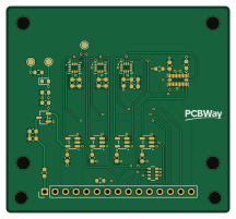
About the IMU TestBoard PCB
IMU TestBoard is an open source PCB design by cvaldess, published on GitHub under the CERN-OHL-S-2.0 license. It is a 4-layer board measuring 54 × 50 mm, with 33 components from 16 distinct parts.
Other key parts include the XC6206P332MR, ICM-45686, LSM6DSV320XTR, ASM330LHHTR and ADXL375BCCZ. By type, the board carries 17 capacitors, 9 ICs, 4 resistors, 1 connector, 1 diode and 1 inductor.
It belongs with the sensors designs in this gallery.
From the project
Four IMUs (ICM-45686, LSM6DSV320X, ASM330LHH, ADXL375) on one rigid 4-layer PCB for motocross data logging tests. KiCad 10 project and fabrication files.
Four inertial sensors on one small, rigid PCB: TDK ICM-45686, ST LSM6DSV320X, ST ASM330LHH and ADI ADXL375. Because they sit side by side on the same board, all four feel the same shocks, vibration and temperature on a motocross bike, so their data can be compared directly.
The board is a test fixture for AI MotoLogger, a data logger for a motocross bike. The test results decide which IMU goes on the main logger board.
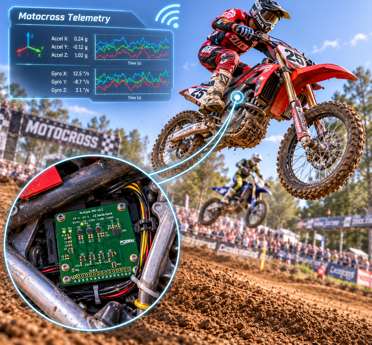
Main components on the IMU TestBoard
IMU TestBoard bill of materials (BOM)
33 components, 16 distinct parts — part numbers from the project's BOM.
| Qty | Part | Footprint | Refs |
|---|---|---|---|
| 1 | XC6206P332MR TOREX | SOT-23-3 | U1 |
| 1 | ICM-45686 TDK InvenSense | LGA-14_3x2.5mm_P0.5mm_LayoutBorder3x4y | U2 |
| 1 | LSM6DSV320XTR STMicroelectronics | LGA-14_3x2.5mm_P0.5mm_LayoutBorder3x4y | U3 |
| 1 | ASM330LHHTR STMicroelectronics | LGA-14_3x2.5mm_P0.5mm_LayoutBorder3x4y | U4 |
| 1 | ADXL375BCCZ Analog Devices | LGA-14_3x5mm_P0.8mm_LayoutBorder1x6y | U5 |
| 4 | SN74LVC1G32DBVR TI | SOT-23-5 | U6, U7, U8, U9 |
| 1 | a la Nucleo - | PinHeader_1x15_P2.54mm_Vertical | J1 |
| 1 | LTST-C191KGKT LED Green Lite-On | LED_0603_1608Metric | D1 |
| 1 | CBW160808U601T 600R@100MHz FH | L_0603_1608Metric | FB1 |
| 3 | CL10A106KP8NNNC 10uF Samsung | C_0603_1608Metric | C1, C4, C10 |
| 3 | CL10B105KA8NNNC 1uF Samsung | C_0603_1608Metric | C2, C3, C12 |
| 11 | CL10B104KB8NNNC 100nF Samsung | C_0603_1608Metric | C5, C6, C7, C8, C9, C11, C13, C14 +3 |
| 1 | RC0603FR-07470RL 470R YAGEO | R_0603_1608Metric | R1 |
| 1 | RC0603FR-0733RL 33R YAGEO | R_0603_1608Metric | R2 |
| 1 | RC0603JR-070RL 0R YAGEO | R_0603_1608Metric | R3 |
| 1 | YC164-FR-0710KL 4x10k YAGEO | R_Array_Convex_4x0603 | RN1 |
IMU TestBoard design files
The KiCad project lives in the cvaldess/IMU_TestBoard repository on GitHub; these links point at the commit this page was built from.
IMU TestBoard: common questions
How big is the IMU TestBoard PCB?
The IMU TestBoard measures 54 × 50 mm, has 4 copper layers and is 1.6 mm thick.
How many components are on the IMU TestBoard?
33 components, from 16 distinct parts, with part numbers taken from the project's own BOM. The full bill of materials is listed on this page.
Where can I download the IMU TestBoard design files?
From the cvaldess/IMU_TestBoard repository on GitHub, which has the KiCad layout, the schematic and the BOM; the links under Design files point to each one.
Can I use the IMU TestBoard design in my own project?
Yes, under the terms of its CERN-OHL-S-2.0 license, which cvaldess chose for the repository.
Similar boards
Sensor smd
scottbez1
40 × 20 mm5 parts2LApache-2.04.2k
Sensors
StuckAtPrototype
15.2 × 9 mm14 parts4LApache-2.03.8k
Microphone
Mentra-Community
5.5 × 6.1 mm6 parts2LMIT1.2k
TemperaturePCB PANEL
stuartpittaway
116 × 75.5 mm178 parts2LCC-BY-NC-4.01.1k
Pots
shanteacontrols
390 × 93 mm75 parts2LApache-2.0956
USB
52 × 12.6 mm6 parts2LApache-2.0956