
FlySensei Stack RPi

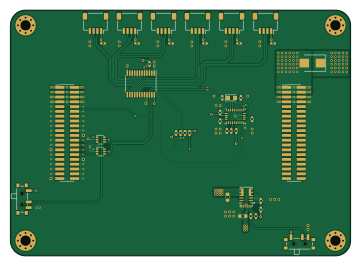
About the FlySensei Stack RPi PCB
FlySensei Stack RPi is an open source AVR/Arduino PCB design by denjos007, published on GitHub. It is a 4-layer board measuring 90 × 65 mm, with 45 components from 30 distinct parts.
Its main chip is the ATTINY85V-10SU, from the AVR/Arduino family. Other key parts include the BNO055, VL53L0CXV0DH/1, G313-06329-00, TPD4EUSB30DQAR and RT9742GGJ5. By type, the board carries 13 capacitors, 12 resistors, 6 ICs, 4 connectors, 2 switches and 1 crystal.
From the project
PCB Design for the Stacked design for Blimp Controller
PCB design of stackable controllers for blimps
Each stack contains a specified function for controlling a blimp
Main components on the FlySensei Stack RPi
FlySensei Stack RPi bill of materials (BOM)
45 components, 30 distinct parts — part numbers from the project's BOM.
| Qty | Part | Footprint | Refs |
|---|---|---|---|
| 1 | BNO055 Hirose Electric Co Ltd | LGA-28_5.2x3.8mm_P0.5mm | U1 |
| 1 | ATTINY85V-10SU TCA9548APWR Microchip Technology | TSSOP-24_4.4x7.8mm_P0.65mm | U2 |
| 1 | VL53L0CXV0DH/1 VL53L0CXV0DH_1 STMicroelectronics | ST_VL53L1x | U3 |
| 1 | G313-06329-00 MPM3610 Google Coral | MPM3610_QFN-20_5x3mm | U4 |
| 1 | TPD4EUSB30DQAR TS5A3159ADCKR Texas Instruments | SOT-363_SC-70-6 | U9 |
| 1 | RT9742GGJ5 TS5A3159ADCKR Richtek USA Inc. | SOT-363_SC-70-6 | U10 |
| 1 | Crystal | Crystal_SMD_2012-2Pin_2.0x1.2mm_HandSoldering | Y1 |
| 1 | Conn_02x20_Odd_Even_Male | PinHeader_2x20_P1.27mm_Vertical_SMD | J1 |
| 1 | USB4105-GF-A Conn_02x20_Odd_Even_Female GCT | PinHeader_2x20_P1.27mm_Vertical_SMD | J2 |
| 1 | FTSH-120-01-F-DV Conn_02x20_Odd_Even_Male Samtec Inc. | PinHeader_2x20_P1.27mm_Vertical_SMD | J3 |
| 1 | CLP-120-02-L-D Conn_02x20_Odd_Even_Female Samtec Inc. | PinHeader_2x20_P1.27mm_Vertical_SMD | J4 |
| 6 | JST_SH_SM04 | JST_SH_SM04B-SRSS-TB_1x04-1MP_P1.00mm_Horizontal | LR1, LR2, LR3, LR4, LR5, LR6 |
| 1 | EVQ-PUL02K SW_SPDT Panasonic Electronic Components | SW_SPDT_PCM12 | SW1 |
| 1 | PCM12SMTR SW_SPDT C&K | SW_SPDT_PCM12 | SW2 |
| 1 | 150060VS75000 D_SCHTKY Würth Elektronik | D_SMB | D1 |
| 8 | GRT155R71C104KE01J 0u1F Murata Electronics | C_0402_1005Metric | C1, C4, C5, C6, C7, C8, C9, C10 |
| 2 | GRT155R71C104KE01J 22pF Murata Electronics | C_0402_1005Metric | C2, C3 |
| 1 | CL10A226MO7JZNC 0u1F Samsung Electro-Mechanics | C_0402_1005Metric | C11 |
| 1 | GRT188C8YA105KE13D 10uF Murata Electronics | C_0603_1608Metric | C12 |
| 1 | GRM21BC8YA106ME11L 22uF Murata Electronics | C_0603_1608Metric | C13 |
Show 10 more
| Qty | Part | Footprint | Refs |
|---|---|---|---|
| 1 | ERA-2AED271X 0K Panasonic Electronic Components | R_0402_1005Metric | R1 |
| 3 | ERA-2AED271X 10K Panasonic Electronic Components | R_0402_1005Metric | R2, R3, R4 |
| 1 | ERA-2AED472X 0K Panasonic | R_0402_1005Metric | R5 |
| 1 | ERJ-2RKF9093X 10K Panasonic Electronic Components | R_0402_1005Metric | R6 |
| 1 | RT0402BRD0751KL 10K Yageo | R_0402_1005Metric | R7 |
| 1 | RC0402FR-0710RL 10K Yageo | R_0402_1005Metric | R8 |
| 1 | RT0402BRD0754K9L 55K Yageo | R_0402_1005Metric | R9 |
| 1 | RT0402BRD0762KL 62K Yageo | R_0402_1005Metric | R10 |
| 1 | RK73H1ETTP2002F 75K KOA Speer Electronics, Inc. | R_0402_1005Metric | R11 |
| 1 | MCR01MZPF1202 24K Rohm Semiconductor | R_0402_1005Metric | R12 |
FlySensei Stack RPi design files
The KiCad project lives in the denjos007/FlySensei_Stack_ECAD repository on GitHub; these links point at the commit this page was built from.
FlySensei Stack RPi: common questions
What microcontroller does the FlySensei Stack RPi use?
The FlySensei Stack RPi is built around the ATTINY85V-10SU, from the AVR/Arduino family.
How big is the FlySensei Stack RPi PCB?
The FlySensei Stack RPi measures 90 × 65 mm, has 4 copper layers and is 1.18 mm thick.
How many components are on the FlySensei Stack RPi?
45 components, from 30 distinct parts, with part numbers taken from the project's own BOM. The full bill of materials is listed on this page.
Where can I download the FlySensei Stack RPi design files?
From the denjos007/FlySensei_Stack_ECAD repository on GitHub, which has the KiCad layout, the schematic and the BOM; the links under Design files point to each one.
Can I use the FlySensei Stack RPi design in my own project?
The repository has no license, so all rights stay with denjos007. Use it as a reference, and ask the author before reusing the design.
Can I test firmware for the FlySensei Stack RPi without the hardware?
Yes. HardLabs builds a simulation of the board from its netlist and BOM, so you can run and debug AVR/Arduino firmware against it before you order a PCB.
More boards in FlySensei_Stack_ECAD
Similar boards
 AVR/Arduino
V4
stuartpittaway
30 × 50 mm38 parts2LCC-BY-NC-4.01.1k AVR/Arduino
ModuleV450
30 × 61.4 mm39 parts2LCC-BY-NC-4.01.1k AVR/Arduino
Easyduino Atmega
Hanqaqa
68.8 × 53.6 mm35 parts4LCERN-OHL-P-2.0746 AVR/Arduino
Easyduino Atmega Nano
43.4 × 18 mm30 parts4LCERN-OHL-P-2.0746 AVR/Arduino
UsbGpib
xyphro
54 × 15 mm21 parts2LMIT683 AVR/Arduino
Lumberjack
peej
284.7 × 94.2 mm149 parts2LMIT402