
Riscduino Debug

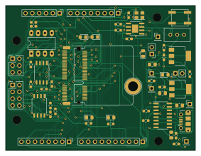
About the Riscduino Debug PCB
Riscduino Debug is an open source PCB design by dineshannayya, published on GitHub under the Apache-2.0 license. It is a 2-layer board measuring 70.6 × 53.7 mm, with 81 components from 31 distinct parts.
Other key parts include the MAX1232ESA+T, W25Q32JVSS, 23LC1024-I/P, caravel-M.2-card and LM1117S-ADJ. By type, the board carries 32 resistors, 18 capacitors, 11 connectors, 8 ICs, 5 diodes and 2 jumpers.
It belongs with the dev boards & breakouts designs in this gallery.
From the project
Host all the MPW Bring-up related Enviornment
This directory provides instruction and firmware for test project for Stanford University on the chipIgnite 2206 shuttle.
The current version of this document along with firmware example and tools can be found at
https://github.com/efabless/caravel_board/tree/main/stanford#readme
The development board provides an easy way to test your project. The board has a socket for installing your part on a breakout board with an M.2 edge connector. Remove the screw to insall or replace the breakout board module. The board inserted into a ZIF connector at a 45 deg angle. It is then pressed down and…
Main components on the Riscduino Debug
Riscduino Debug bill of materials (BOM)
81 components, 31 distinct parts.
| Qty | Part | Footprint | Refs |
|---|---|---|---|
| 1 | MAX1232ESA+T | SOIC-8-1EP_3.9x4.9mm_P1.27mm_EP2.29x3mm | U1 |
| 2 | W25Q32JVSS | SOIC-8_5.23x5.23mm_P1.27mm | U2, U4 |
| 1 | 23LC1024-I/P | DIP-8_W7.62mm_LongPads | U3 |
| 1 | caravel-M.2-card | M.2-CONNECTOR-E | U5 |
| 1 | LM1117S-ADJ | SOT-223-3_TabPin2 | U6 |
| 1 | LM1117MP-3.3 | SOT-223-3_TabPin2 | U7 |
| 1 | CH340C | SOIC-16_3.9x9.9mm_P1.27mm | U8 |
| 1 | ASE-10.000MHZ-LC-T | Crystal_SMD_Abracon_ABM8G-4Pin_3.2x2.5mm | X1 |
| 1 | Conn_01x06_Pin | PinHeader_1x06_P2.54mm_Vertical | J1 |
| 2 | Conn_01x08_Pin | PinHeader_1x08_P2.54mm_Vertical | J2, J9 |
| 4 | Conn_01x01 | PinHeader_1x01_P2.54mm_Vertical | J3, J6, J7, J8 |
| 1 | Conn_02x04_Odd_Even | PinHeader_2x04_P2.54mm_Vertical | J4 |
| 1 | ISP | PinHeader_2x03_P2.54mm_Vertical | J5 |
| 1 | USB_B_Micro | USB_Micro-B_Molex-105017-0001 | J10 |
| 1 | Conn_01x10_Pin | PinHeader_1x10_P2.54mm_Vertical | J11 |
| 1 | MICROMOD-Standoff | MicroMod-Standoff | H3 |
| 2 | Jumper_2 | PinHeader_1x02_P2.54mm_Vertical | JP1, JP2 |
| 1 | 500 Ohm Trim Pot | Potentiometer_Bourns_3296W_Vertical | RV1 |
| 1 | 4Pin Round Button SPST Straight Tactile Switch SMD - TS4550TP | SW_SPST_EVPBF_TS4550TP | SW1 |
| 1 | TestPoint | PinHeader_1x01_P2.54mm_Vertical | TP1 |
Show 11 more
| Qty | Part | Footprint | Refs |
|---|---|---|---|
| 3 | GREEN LED | LED_0805_2012Metric_Pad1.15x1.40mm_HandSolder | D1, D4, D5 |
| 1 | RED LED | LED_0805_2012Metric_Pad1.15x1.40mm_HandSolder | D3 |
| 1 | BLUE LED | LED_0805_2012Metric_Pad1.15x1.40mm_HandSolder | D6 |
| 13 | 0.1uF | C_0603_1608Metric_Pad1.08x0.95mm_HandSolder | C1, C2, C3, C4, C5, C8, C9, C11 +5 |
| 3 | 10uF | C_0805_2012Metric_Pad1.18x1.45mm_HandSolder | C6, C7, C12 |
| 2 | 22uF | C_0805_2012Metric_Pad1.18x1.45mm_HandSolder | C10, C15 |
| 15 | 10K | R_0603_1608Metric_Pad0.98x0.95mm_HandSolder | R1, R2, R3, R4, R5, R6, R7, R19 +7 |
| 3 | DNI | R_0603_1608Metric_Pad0.98x0.95mm_HandSolder | R8, R15, R16 |
| 4 | 0E | R_0603_1608Metric_Pad0.98x0.95mm_HandSolder | R9, R10, R14, R32 |
| 7 | 470 Ohm | R_0603_1608Metric_Pad0.98x0.95mm_HandSolder | R11, R12, R13, R17, R18, R20, R21 |
| 3 | 0 Ohm | R_0603_1608Metric_Pad0.98x0.95mm_HandSolder | R22, R23, R24 |
Riscduino Debug design files
The KiCad project lives in the dineshannayya/riscduino_bringup repository on GitHub; these links point at the commit this page was built from.
Riscduino Debug: common questions
How big is the Riscduino Debug PCB?
The Riscduino Debug measures 70.6 × 53.7 mm, has 2 copper layers and is 1.61544 mm thick.
How many components are on the Riscduino Debug?
81 components, from 31 distinct parts. The full bill of materials is listed on this page.
Where can I download the Riscduino Debug design files?
From the dineshannayya/riscduino_bringup repository on GitHub, which has the KiCad layout and the schematic; the links under Design files point to each one.
Can I use the Riscduino Debug design in my own project?
Yes, under the terms of its Apache-2.0 license, which dineshannayya chose for the repository.
More boards in riscduino_bringup
Similar boards
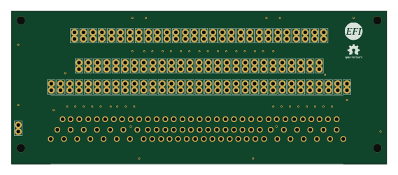
88 Pin Vag Breakout
rusefi
142 × 58 mm91 parts2LGPL-3.01.2k
134pin 7-967288-1
139.7 × 73.7 mm38 parts2LGPL-3.01.2k
Breakout 60pin EEC-IV
139.7 × 62.2 mm15 parts2LGPL-3.01.2k
Breakout 112pin Connector
174 × 58 mm39 parts2LGPL-3.01.2k
Eecv breakout
140.8 × 53.7 mm9 parts4LGPL-3.01.2k
Rj45 breakout
rene-dev
15.2 × 53.8 mm3 parts2LGPL-3.0979