
Control

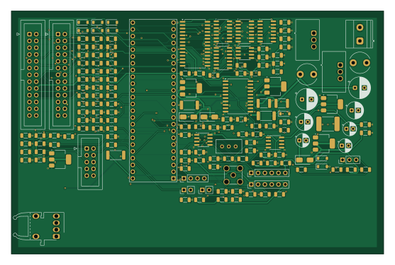
About the Control PCB
Control is an open source NXP PCB design by driador, published on GitHub under the CERN-OHL-W-2.0 license. It is a 4-layer board measuring 139 × 91 mm, with 166 components from 59 distinct parts.
Its main chip is the Teensy 4.1, from the NXP family. Other key parts include the TSR 3-2450N, TSR 2-24120N, AMS1117-3.3, 74HC08 and 74HC32. By type, the board carries 83 resistors, 36 capacitors, 13 ICs, 12 diodes, 11 connectors and 4 transistors.
It belongs with the rf & radio designs in this gallery.
From the project
1500 W automated antenna tuner for a 170 ft doublet on 600 Ω ladder line, 160–10 m: a T-network with vacuum capacitors and a roller inductor, Teensy 4.1 firmware, KiCad boards, build123d/FreeCAD drawings and NEC-2 models. Open hardware (CERN-OHL-W v2); firmware GPL-3.0.
KF0OWR's homebuilt 1500 W remote balanced tuner for a doublet on 160–10 m. It uses a 34 µH roller inductor, two vacuum capacitors and Tohtsu relays, and sits in a wall-mounted 16 × 16 × 24″ cabinet. The design log is the source of truth. Everything else in this repo (CAD, drawings, NEC models, KiCad boards) supports it, and the log cites these files by their repo paths.
Main components on the Control
Control bill of materials (BOM)
166 components, 59 distinct parts.
| Qty | Part | Footprint | Refs |
|---|---|---|---|
| 1 | TSR 3-2450N | Converter_DCDC_TRACO_TSR2-24xxN_TSR2-24xxxN_THT | U1 |
| 1 | TSR 2-24120N | Converter_DCDC_TRACO_TSR2-24xxN_TSR2-24xxxN_THT | U2 |
| 1 | AMS1117-3.3 | SOT-223-3_TabPin2 | U3 |
| 1 | 74HC08 | SOIC-14_3.9x8.7mm_P1.27mm | U4 |
| 1 | 74HC32 | SOIC-14_3.9x8.7mm_P1.27mm | U5 |
| 1 | 74HC21 | SOIC-14_3.9x8.7mm_P1.27mm | U6 |
| 1 | 74HC14 | SOIC-14_3.9x8.7mm_P1.27mm | U7 |
| 1 | LMC555 | SOIC-8_3.9x4.9mm_P1.27mm | U8 |
| 1 | 74HC373 | SOIC-20W_7.5x12.8mm_P1.27mm | U9 |
| 1 | MCP23017 | SOIC-28W_7.5x17.9mm_P1.27mm | U10 |
| 1 | LM393 | SOIC-8_3.9x4.9mm_P1.27mm | U11 |
| 1 | MCP6002 | SOIC-8_3.9x4.9mm_P1.27mm | U12 |
| 1 | HFBR-1521Z | AGILENT_HFBR-152x | U13 |
| 1 | Teensy 4.1 | Teensy4.1 | A1 |
| 4 | IRLL2705TRPBF | SOT-223-3_TabPin2 | Q1, Q2, Q3, Q4 |
| 1 | 24V in | TerminalBlock_Phoenix_MKDS-1,5-2-5.08_1x02_P5.08mm_Horizontal | J1 |
| 1 | J-A logic | IDC-Header_2x13_P2.54mm_Vertical | J2 |
| 1 | J-B sampler | IDC-Header_2x13_P2.54mm_Vertical | J3 |
| 1 | J-E RF tank | IDC-Header_2x05_P2.54mm_Vertical | J4 |
| 1 | J-F blower | PinHeader_1x03_P2.54mm_Vertical | J5 |
Show 39 more
| Qty | Part | Footprint | Refs |
|---|---|---|---|
| 1 | Nextion | PinHeader_1x04_P2.54mm_Vertical | J6 |
| 1 | encoder 1 | PinHeader_1x06_P2.54mm_Vertical | J7 |
| 1 | encoder 2 | PinHeader_1x06_P2.54mm_Vertical | J8 |
| 1 | bypass key | PinHeader_1x02_P2.54mm_Vertical | J9 |
| 1 | recovery button | PinHeader_1x02_P2.54mm_Vertical | J10 |
| 1 | SMA /1024 in | SMA_Amphenol_132134-11_Vertical | J11 |
| 1 | 2920L185DR | Fuse_2920_7451Metric | F1 |
| 2 | MF-MSMF030/60X-2 | Fuse_1812_4532Metric | F2, F3 |
| 1 | 10k 3296W | Potentiometer_Bourns_3296W_Vertical | RV1 |
| 9 | BAT42W | D_SOD-123 | D1, D2, D3, D4, D5, D6, D10, D11 +1 |
| 2 | S1M | D_SMA | D7, D8 |
| 1 | SS14 | D_SMA | D9 |
| 2 | 1u 07HCP | L_Radial_D7.8mm_P5.00mm_Fastron_07HCP | L1, L2 |
| 1 | 220u 35V low-ESR | CP_Radial_D8.0mm_P3.50mm | C1 |
| 1 | 150u 35V | CP_Radial_D8.0mm_P3.50mm | C2 |
| 1 | 100u 35V | CP_Radial_D6.3mm_P2.50mm | C3 |
| 1 | 47u 10V | CP_Radial_D5.0mm_P2.50mm | C4 |
| 1 | 22u 25V | CP_Radial_D5.0mm_P2.50mm | C5 |
| 1 | 100u 10V | CP_Radial_D6.3mm_P2.50mm | C6 |
| 17 | 100n | C_1206_3216Metric | C7, C8, C16, C17, C18, C19, C23, C24 +9 |
| 9 | 10n | C_1206_3216Metric | C9, C10, C11, C12, C13, C15, C20, C21 +1 |
| 1 | 1n | C_1206_3216Metric | C14 |
| 1 | 4.7u 25V | CP_Radial_D5.0mm_P2.50mm | C22 |
| 1 | 10n C0G | C_1206_3216Metric | C25 |
| 1 | 100n C0G | C_1206_3216Metric | C27 |
| 19 | 47 | R_1206_3216Metric | R1, R2, R3, R4, R5, R6, R7, R8 +11 |
| 25 | 10k | R_1206_3216Metric | R20, R21, R22, R23, R24, R25, R34, R38 +17 |
| 1 | 1M | R_1206_3216Metric | R26 |
| 17 | 1k | R_1206_3216Metric | R27, R28, R29, R30, R31, R33, R35, R41 +9 |
| 5 | 100k | R_1206_3216Metric | R32, R37, R74, R82, R83 |
| 1 | 10M | R_1206_3216Metric | R36 |
| 1 | 3k9 | R_1206_3216Metric | R42 |
| 1 | 56k | R_1206_3216Metric | R43 |
| 6 | 100 | R_1206_3216Metric | R45, R49, R59, R63, R64, R77 |
| 2 | 1R 1W | R_2512_6332Metric | R47, R51 |
| 2 | 4k7 | R_1206_3216Metric | R72, R73 |
| 1 | 6k8 | R_1206_3216Metric | R76 |
| 1 | 56 1W | R_2512_6332Metric | R79 |
| 1 | 560k | R_1206_3216Metric | R81 |
Control design files
The KiCad project lives in the driador/antenna-tuner repository on GitHub; these links point at the commit this page was built from.
- Layoutkicad/control.kicad_pcb
- Schematickicad/control.kicad_sch
Control: common questions
What microcontroller does the Control use?
The Control is built around the Teensy 4.1, from the NXP family.
How big is the Control PCB?
The Control measures 139 × 91 mm, has 4 copper layers and is 1.6 mm thick.
How many components are on the Control?
166 components, from 59 distinct parts. The full bill of materials is listed on this page.
Where can I download the Control design files?
From the driador/antenna-tuner repository on GitHub, which has the KiCad layout and the schematic; the links under Design files point to each one.
Can I use the Control design in my own project?
Yes, under the terms of its CERN-OHL-W-2.0 license, which driador chose for the repository.
Can I test firmware for the Control without the hardware?
Yes. HardLabs builds a simulation of the board from its netlist and BOM, so you can run and debug NXP firmware against it before you order a PCB.
More boards in antenna-tuner
Similar boards
 NXP
32Bit shift register
MaltWhiskey
100 × 54 mm56 parts4LNo license763 NXP
Mega-Cube-Board
200 × 54 mm100 parts4LNo license763 NXP
MCL6809
MicroCoreLabs
32.3 × 61 mm7 parts4LNo license532 NXP
MCL68
31.6 × 84.1 mm13 parts4LNo license532 NXP
MCL65+
72.6 × 64.1 mm6 parts2LNo license532 NXP
MCLZ8
37.1 × 61.5 mm6 parts4LNo license532