
71 open source boards using the MCP23017
Real designs built with the MCP23017, from public GitHub projects: a quick way to see how others power, decouple and connect it. Each board comes with its KiCad files, full parts list and a render — and you can simulate its firmware on HardLabs.
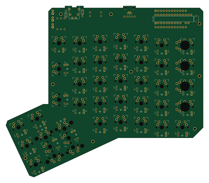
ErgoDone
ktec-hq
182.8 × 158.9 mm141 partsGPL-3.0123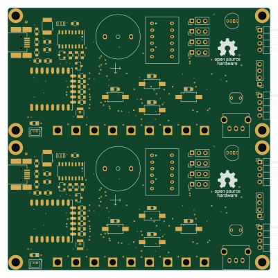 ESP8266
Wifi PB panel
AntonioMR
100 × 100 mm162 parts2LNo license29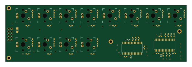
Buttons
jsjolund
158.8 × 49.6 mm82 parts2LNo license26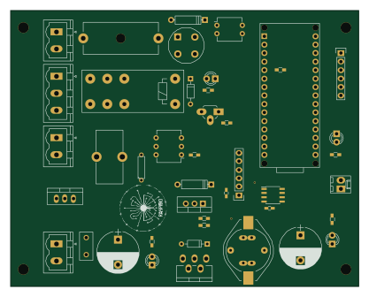 AVR/Arduino
HotAirGun
raspibo
104.1 × 82.6 mm68 parts2LNo license16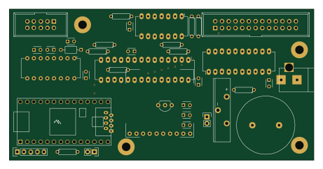 NXP
TeensyBoardZ80
mecparts
115 × 57.2 mm38 parts2LMIT13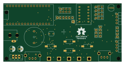
Nano-Play-Board
100 × 49.7 mm107 parts2LNo license12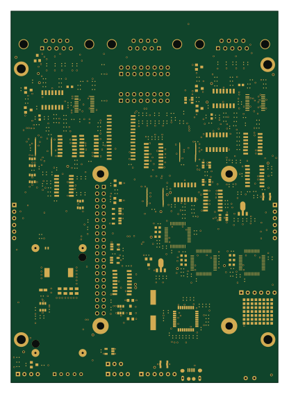 Raspberry Pi
PiPtr
jmlzone
101.6 × 141.7 mm379 parts4LNo license8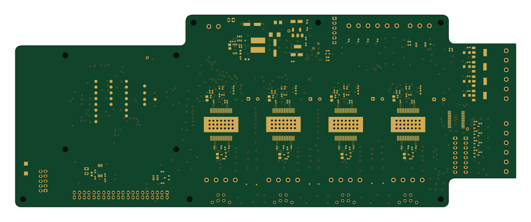 Raspberry Pi
Slushengine modelx
Roboteurs
261 × 100 mm205 parts2LCustom license8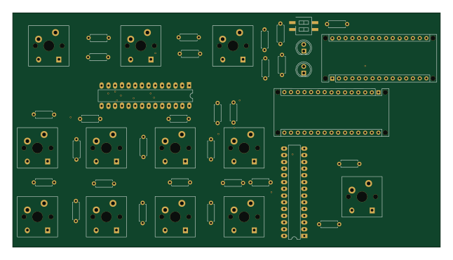
Voctoknopf1
benjaminwand
161.3 × 88.5 mm44 parts2LNo license6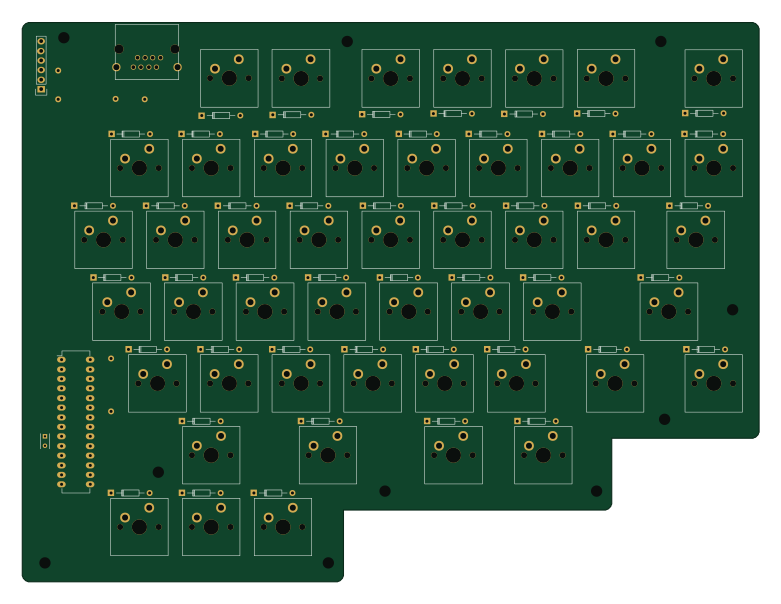
KeyModule-R
cho45
195 × 148 mm100 parts2LNo license5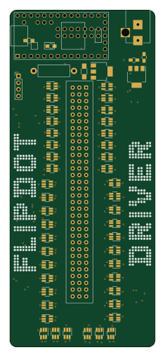 NXP
Driver
augustt198
54.6 × 127 mm62 parts2LNo license4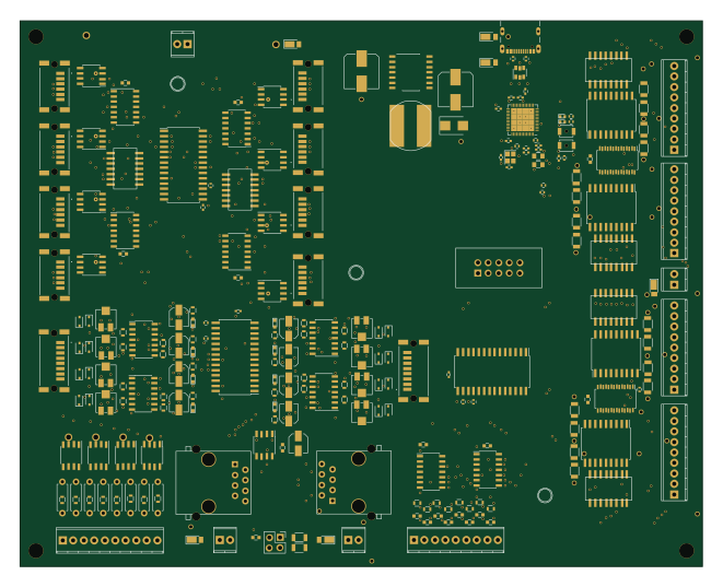 ESP32
ESP32-S3-MegaMultiFunction
RobertPHeller
165.1 × 132.1 mm238 parts2LCC-BY-4.03 ESP32
ESP32-D0WD-V3-ControlStand-V0-0
34.5 × 23.1 mm166 parts2LGPL-3.03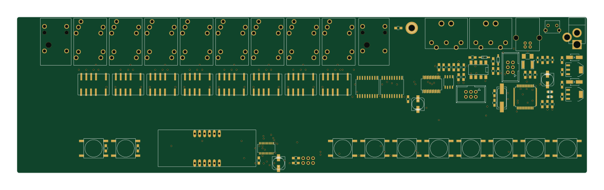 AVR/Arduino
Mls800
blemasle
293.4 × 80.5 mm92 parts2LGPL-3.03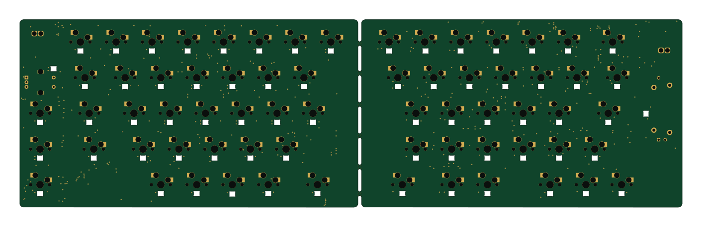 Nordic nRF
Cute-Cat-Split-Keeb
adonutartist
352.5 × 100 mm216 parts2LNo license1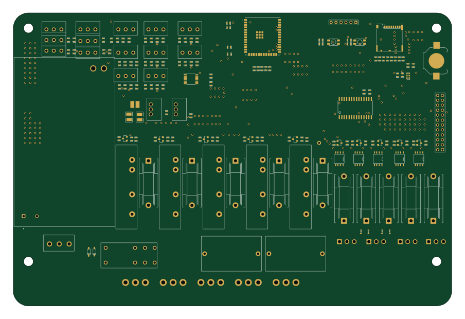 ESP32
Back Panel
coastalwarming
225.6 × 150.6 mm174 parts2LNo license1
Io
tkleisas
180 × 210 mm135 parts2LMIT1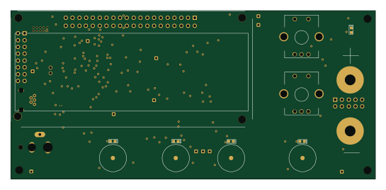 STM32
Lps display rev 10
jerryok826
136.1 × 62.7 mm130 parts2LMIT1
Z8lpanel
mrieker
262.3 × 16.2 mm54 parts6LNo license1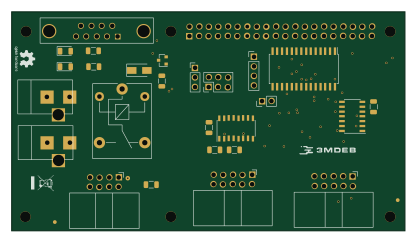 Raspberry Pi
RTE-for-RPI-Schematics
3mdeb
104 × 57.9 mm31 parts2LCERN-OHL-1.21
Mrmeeseeks RevA
d4rkwyng
49.6 × 62.4 mm21 parts2LMIT1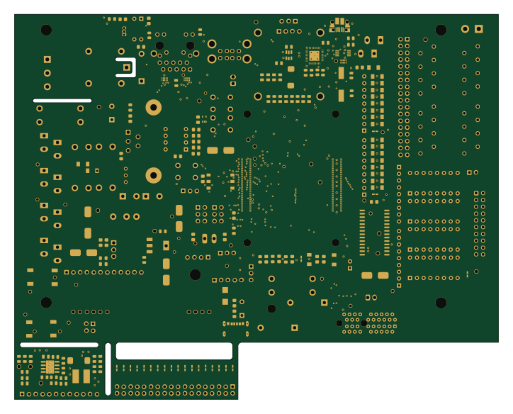 Raspberry Pi
CrallyBoard
cruunnerr
180.7 × 143.8 mm226 parts2LNo license0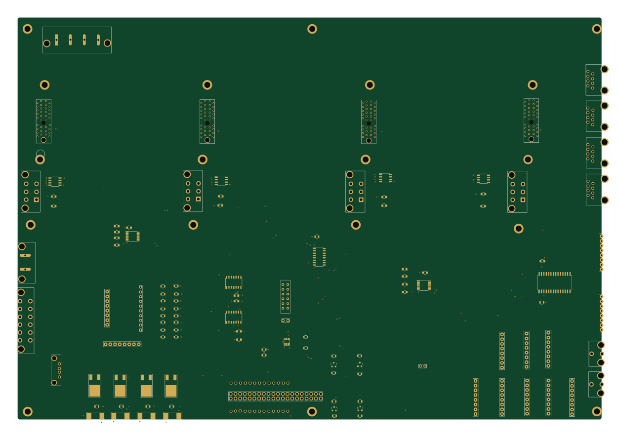
Ruggedpod electronics
RuggedPOD
312.8 × 215.4 mm141 parts4LNo license0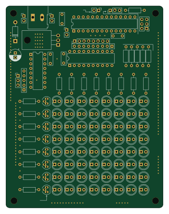
8x8 Matrix Eduboard
hkzlab
85.1 × 109.2 mm115 parts2LCC-BY-NC-4.00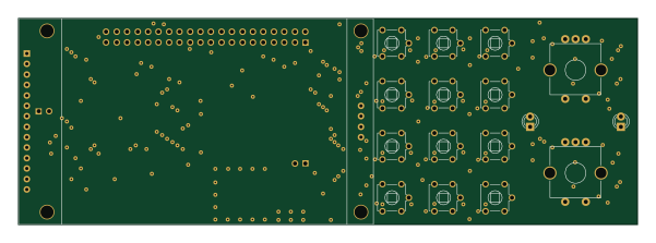
Universal IO
celeritous
150 × 50 mm107 parts2LNo license0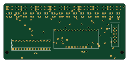
LTM - PCB Sensor 16 titik
Mervs111
110 × 51 mm80 parts2LNo license0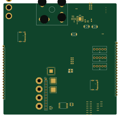 RP2040/RP2350
PCB-PD
Taran-the-Idiot
105 × 103.7 mm69 parts2LMIT0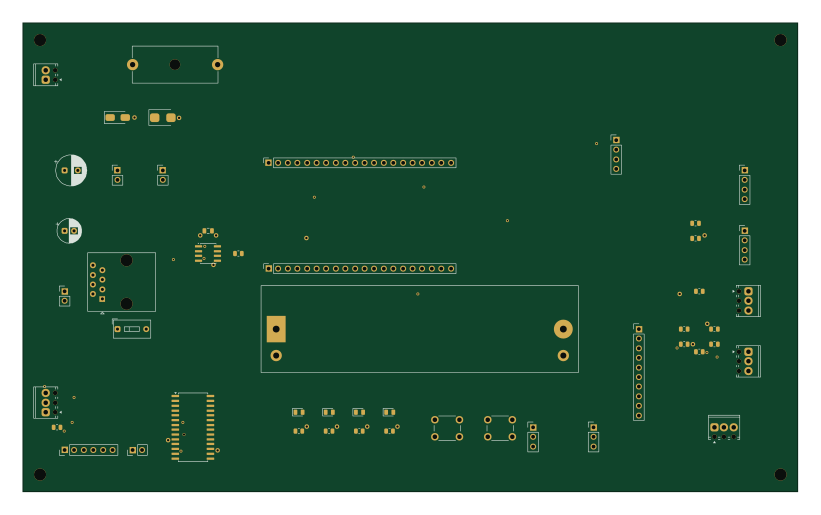
Ews tbeam mainboard
venougm
205 × 124 mm49 parts2LNo license0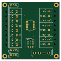
Switchero
FunkFeuer
62 × 61 mm27 parts2LCustom license0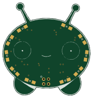
Mooncake RevA
46 × 48.4 mm23 parts2LMIT0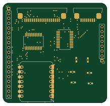 RP2040/RP2350
Olivetti-Philos-44-Retro-Build
salvas2011
54.5 × 52 mm13 parts2LNo license0- schematic only · 17 parts
Little Voicemail
guinius
17 partsGPL-3.00 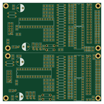
RelayControl
profdc9
100 × 100 mm180 parts2LNo license59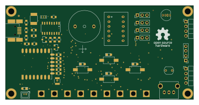 ESP8266
Wifi PB
100 × 49.7 mm161 parts2LNo license29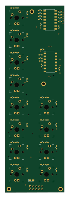
3 Buttons
50 × 158.8 mm80 parts2LNo license26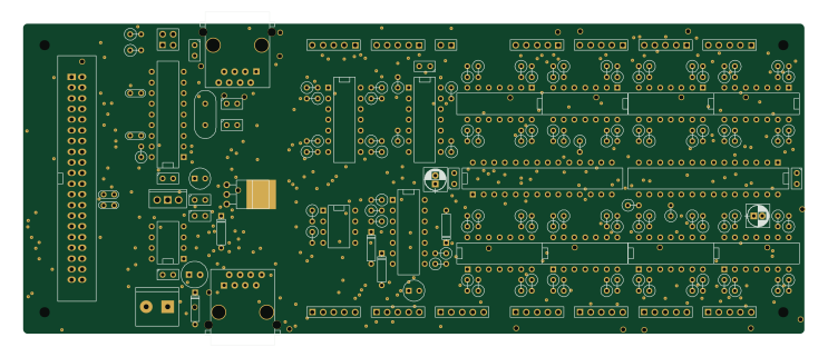
FullInterlockingPlantCANPower
185.4 × 73.7 mm151 parts2LCC-BY-4.024
How designs wire the MCP23017
Read from the KiCad layouts of 43 open source designs, one per repository: what each pin of the MCP23017 connects to, and the resistors, capacitors and other passives placed on it.
- The A1 pin is tied to GND on 31 of 43 designs (not connected on 2, 5V on 2, a signal on 8).
- The A0 pin is tied to GND on 30 of 43 designs (not connected on 2, 5V on 2, a signal on 9).
- The A2 pin is tied to GND on 30 of 43 designs (5V on 3, a signal on 10).
- The INTB pin is left unconnected on 29 of 43 designs (a signal on 14).
| Pin | Connected to | Parts on the pin |
|---|---|---|
| VDDpin 9 | Connected to: 3.3V 86% |
|
| VSSpin 10 | Connected to: GND 93% | — |
| NCpin 11, 14 | Connected to: Not connected 93% | — |
| SCKpin 12 | Connected to: A connector 60%, MCP23017 26% |
|
| SDApin 13 | Connected to: A connector 60%, MCP23017 26% |
|
| A0pin 15 | Connected to: GND 70% · a signal 21% | — |
| A1pin 16 | Connected to: GND 72% · a signal 19% | — |
| A2pin 17 | Connected to: GND 70% · a signal 23% | — |
| RESETpin 18 | Connected to: A connector 28% · 3.3V 35% |
|
| INTBpin 19 | Connected to: Not connected 67% · a signal 33% | — |
| INTApin 20 | Connected to: Not connected 65% · a signal 35% | — |
| GPA4pin 25 | Connected to: Signal 86% |
|
15 more pins vary from design to design. Connections count pins, parts count designs; values in brackets are how many parts had that value. Designs read include ErgoDone by ktec-hq, OptoisolatedRelay by profdc9, Wifi PB by AntonioMR and 0 Buttons PCB by jsjolund.
The MCP23017 in open source designs
The gallery holds 71 open source boards using the MCP23017 from 45 GitHub repositories; a typical one measures about 104.1 × 81.3 mm and carries around 69 components.
94% are two-layer designs, the rest use four layers or more, and 42% carry an open source license.
The most starred is ErgoDone by ktec-hq.
Parts used alongside the MCP23017
Microcontrollers on boards using the MCP23017
What boards using the MCP23017 are built for
MCP23017: common questions
Where can I find a MCP23017 reference design?
Each of the 71 boards on this page is a real design using the MCP23017. Open one to see how it is wired up, with the full BOM, a render of the layout and links to its KiCad files.
How is the MCP23017 A1 pin connected?
The A1 pin is tied to GND on 31 of 43 designs (not connected on 2, 5V on 2, a signal on 8). Counted from the KiCad layouts of 43 open source designs using the MCP23017.
How is the MCP23017 A0 pin connected?
The A0 pin is tied to GND on 30 of 43 designs (not connected on 2, 5V on 2, a signal on 9). Counted from the KiCad layouts of 43 open source designs using the MCP23017.
How is the MCP23017 A2 pin connected?
The A2 pin is tied to GND on 30 of 43 designs (5V on 3, a signal on 10). Counted from the KiCad layouts of 43 open source designs using the MCP23017.
What parts are used alongside the MCP23017?
The MAX3232, ULN2803A, 24LC256, 40106 and 74LS245 appear in the most repositories here.
Which microcontrollers do boards using the MCP23017 use?
Most are built on Raspberry Pi (5), ESP32 (5), ESP8266 (3) and RP2040/RP2350 (3).
How big is a typical board using the MCP23017?
The median is 104.1 × 81.3 mm, and 94% are two-layer designs.
What is the most popular open source board using the MCP23017?
By GitHub stars, ErgoDone by ktec-hq, with 123 stars.
Can I simulate one of these boards using the MCP23017 before building it?
Yes. HardLabs turns a board's netlist and BOM into a working simulation, so you can boot and test firmware against it with no hardware on your desk.