
ESP-HI-PLUS

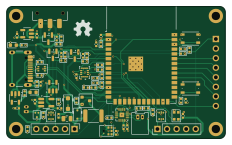
About the ESP-HI-PLUS PCB
ESP-HI-PLUS is an open source RP2040/RP2350 PCB design by dyu134, published on GitHub. It is a 4-layer board measuring 58 × 35 mm, with 83 components from 58 distinct parts.
Its main chip is the RP2040, from the RP2040/RP2350 family. Other key parts include the W25Q16JVSS, MAX40200AUK, MAX17049, LSM6DSV16X and TLV75733PDBV. By type, the board carries 32 resistors, 19 capacitors, 11 diodes, 7 ICs, 5 connectors and 3 switches.
It belongs with the audio, displays & leds and sensors designs in this gallery.
From the project
An AI-enabled voice assistant with on-screen interaction, built around the ESP32-S3-WROOM-1. The board integrates a microphone, speaker amplifier, IMU, 2" IPS LCD, MicroSD card slot, and USB-C with on-board Li-ion battery charging, and exposes two 5-pin magnetic pogo-pin connecto
An AI-enabled voice assistant with on-screen interaction, built around the ESP32-S3-WROOM-1. The board integrates a microphone, speaker amplifier, IMU, 2" IPS LCD, MicroSD card slot, and USB-C with on-board Li-ion battery charging, and exposes two 5-pin magnetic pogo-pin connectors for attaching various sub-modules. Designed for handheld and wearable applications that combine on-device conversational AI, audio capture/playback, display feedback, and motion sensing.
Main components on the ESP-HI-PLUS
ESP-HI-PLUS bill of materials (BOM)
83 components, 58 distinct parts — part numbers from the project's BOM.
| Qty | Part | Footprint | Refs |
|---|---|---|---|
| 1 | W25Q16JVSS MAX40200AUK | SOT-23-5 | U1 |
| 1 | MAX40200AUK ESP32-S3-WROOM-1 | ESP32-S3-WROOM-1 | U2 |
| 1 | RP2040 TLV75733PDBV | SOT-23-5 | U3 |
| 1 | MAX40200AUK TP4065 | SOT-23-5_HandSoldering | U5 |
| 1 | MAX17049 MAX40200AUK | SOT-23-5 | U6 |
| 1 | LSM6DSV16X MAX98357A | TQFN-16-1EP_3x3mm_P0.5mm_EP1.23x1.23mm | U7 |
| 1 | TLV75733PDBV LSM6DSV16X | LGA14_LSM6_STM | U8 |
| 1 | NTK3139P AO3401A | SOT-23 | Q1 |
| 1 | NTK3139P | SOT-723 | Q2 |
| 1 | USB_C_RECEPTACLE_USB2.0_14P USB_C_Receptacle_USB2.0_14P | USB_C_Receptacle_HCTL_HC-TYPE-C-16P-01A | J1 |
| 1 | 2" IPS LCD | PinSocket_1x08_P2.54mm_Vertical | J2 |
| 1 | XT60 PR5L4015-5P-C-F | PinHeader_1x05_P2.54mm_Vertical | J3 |
| 1 | PR5L4015-5P-C-F | PinHeader_1x05_P2.54mm_Vertical | J4 |
| 1 | PR5L5015-5P-C-H Micro_SD_Card | microSD_HC_Hirose_DM3AT-SF-PEJM5 | J5 |
| 1 | Battery_Cell | Molex_PicoBlade_53048-0210_1x02_P1.25mm_Horizontal | BT1 |
| 1 | 2920L1000SL21GRG MF-MSMF200 | Fuse_1812_4532Metric | F1 |
| 1 | Speaker | Molex_PicoBlade_53048-0210_1x02_P1.25mm_Horizontal | LS1 |
| 1 | ICS-43434 | InvenSense_ICS-43434-6_3.5x2.65mm | MK1 |
| 2 | SKRPACE010 | SW_Push_1P1T_NO_Vertical_Wuerth_434133025816 | SW1, SW2 |
| 1 | JS102011SAQN | SW_SPDT_CK_JS102011SAQN | SW3 |
Show 38 more
| Qty | Part | Footprint | Refs |
|---|---|---|---|
| 1 | SK9822-EC20 USBLC6-2P6 | SOT-666 | D1 |
| 1 | USBLC6-2P6 ORANGE | LED_0603_1608Metric | D2 |
| 1 | USBLC6-2P6 RED | LED_0603_1608Metric | D4 |
| 1 | USBLC6-2P6 PMEG4010CEJ | D_SOD-323F | D5 |
| 1 | SMF6.8CA | D_SOD-123F | D6 |
| 2 | USBLC6-2P6 | SOT-666 | D7, D8 |
| 3 | BAT54S | SOT-23 | D9, D10, D11 |
| 1 | WS2812B-2020 | LED_WS2812B-2020_PLCC4_2.0x2.0mm | D12 |
| 1 | 4N7 15p | C_0402_1005Metric | C1 |
| 1 | 1u | C_0402_1005Metric | C2 |
| 4 | 0U1 10u | C_0402_1005Metric | C3, C5, C6, C10 |
| 1 | 10u | C_0402_1005Metric | C4 |
| 3 | 0U1 0u1 | C_0402_1005Metric | C7, C13, C17 |
| 2 | 15P 0u1 | C_0402_1005Metric | C8, C9 |
| 3 | 0u1 | C_0402_1005Metric | C11, C16, C18 |
| 1 | 0U1 100u | C_0805_2012Metric | C12 |
| 1 | 10U 10u | C_0402_1005Metric | C14 |
| 1 | 10U 0u1 | C_0402_1005Metric | C15 |
| 1 | 4n7 | C_0402_1005Metric | C19 |
| 6 | 10k | R_0402_1005Metric | R1, R2, R30, R31, R32, R33 |
| 2 | 5K1 5k1 | R_0402_1005Metric | R3, R4 |
| 1 | 5k1 | R_0402_1005Metric | R5 |
| 1 | 4K7 5k1 | R_0402_1005Metric | R6 |
| 1 | 4K7 100k | R_0402_1005Metric | R7 |
| 1 | 3k3 | R_0402_1005Metric | R8 |
| 1 | 100M 3k3 | R_0402_1005Metric | R9 |
| 1 | 10K 5k1 | R_0402_1005Metric | R10 |
| 1 | 953K 5k1 | R_0402_1005Metric | R11 |
| 1 | 100 100k | R_0402_1005Metric | R12 |
| 1 | 100 10k | R_0402_1005Metric | R13 |
| 1 | 100 2k1 | R_0402_1005Metric | R14 |
| 1 | 100 634k | R_0402_1005Metric | R15 |
| 2 | 10K 100 | R_0402_1005Metric | R17, R18 |
| 2 | 100 | R_0402_1005Metric | R19, R20 |
| 3 | 100k | R_0402_1005Metric | R21, R23, R25 |
| 3 | 33k | R_0402_1005Metric | R22, R24, R26 |
| 1 | 1M | R_0402_1005Metric | R27 |
| 2 | 47k | R_0402_1005Metric | R28, R29 |
ESP-HI-PLUS design files
The KiCad project lives in the dyu134/ESP-HI-PLUS repository on GitHub; these links point at the commit this page was built from.
ESP-HI-PLUS: common questions
What microcontroller does the ESP-HI-PLUS use?
The ESP-HI-PLUS is built around the RP2040, from the RP2040/RP2350 family.
How big is the ESP-HI-PLUS PCB?
The ESP-HI-PLUS measures 58 × 35 mm, has 4 copper layers and is 1.6 mm thick.
How many components are on the ESP-HI-PLUS?
83 components, from 58 distinct parts, with part numbers taken from the project's own BOM. The full bill of materials is listed on this page.
Where can I download the ESP-HI-PLUS design files?
From the dyu134/ESP-HI-PLUS repository on GitHub, which has the KiCad layout, the schematic and the BOM; the links under Design files point to each one.
Can I use the ESP-HI-PLUS design in my own project?
The repository has no license, so all rights stay with dyu134. Use it as a reference, and ask the author before reusing the design.
Can I test firmware for the ESP-HI-PLUS without the hardware?
Yes. HardLabs builds a simulation of the board from its netlist and BOM, so you can run and debug RP2040/RP2350 firmware against it before you order a PCB.
More boards in ESP-HI-PLUS
Similar boards
 RP2040/RP2350
Open Book Abridged Edition
joeycastillo
85 × 115 mm29 parts2LCC-BY-SA-4.08.1k RP2040/RP2350
Corne
foostan
277.2 × 107.5 mm164 parts2LCC-BY-4.07.7k RP2040/RP2350
Corne
277.2 × 107.5 mm164 parts2LCC-BY-4.07.7k RP2040/RP2350
Open Source Smart Glasses
Mentra-Community
93 × 10.5 mm80 parts4LMIT1.2k RP2040/RP2350
MSA
30.5 × 138 mm61 parts2LMIT1.2k RP2040/RP2350
Msa
47.8 × 9.4 mm53 parts2LMIT1.2k