
Input

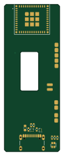
About the Input PCB
Input is an open source ESP32 PCB design by earlynerd, published on GitHub. It is a 4-layer board measuring 21 × 55.9 mm, with 69 components from 40 distinct parts.
Its main chip is the ESP32-C6-MINI-1, from the ESP32 family. Other key parts include the DRV2625YFFR, BQ25186DLHR, TPS63802DLAR, TPD2EUSB30DRTR and M2003FC1AE. By type, the board carries 29 resistors, 20 capacitors, 8 ICs, 4 connectors, 3 switches and 1 module.
From the project
See ../../../docs/main-board-placement.md for constraints and distances. main.kicad_pcb is the applied 70-part checkpoint; placement.png/svg show native pads and courtyard bounds. The active sources are ../../main/. Current acceptance reports are ../project-split/.
See ../../../docs/main-board-placement.md for constraints and distances. main.kicad_pcb is the applied 70-part checkpoint; placement.png/svg show native pads and courtyard bounds. The active sources are ../../main/. Current acceptance reports are ../project-split/.
input.kicadpcb is the user placement with the new Tag-Connect footprint synchronized before optimization. previous.xml and active-latest capture intermediate redraw checks; they are historical. metrics.json is an earlier candidate measurement and is superseded by critical-distances.json and the final native reports.…
Main components on the Input
Input bill of materials (BOM)
69 components, 40 distinct parts.
| Qty | Part | Footprint | Refs |
|---|---|---|---|
| 1 | ESP32-C6-MINI-1 | ESP32-C6-MINI-1 | U1 |
| 1 | DRV2625YFFR DRV2625 Texas Instruments | DRV2625_YFF_9_0.4mm | U3 |
| 1 | BQ25186DLHR BQ25186DLH Texas Instruments | Texas_DLH0010A_WSON-10-1EP_2.2x2mm_P0.4mm_EP0.9x1.5mm | U11 |
| 1 | TPS63802DLAR TPS63802DLA Texas Instruments | TPS63802_DLA0010A | U12 |
| 2 | TPD2EUSB30DRTR TPD2EUSB30 Texas Instruments | Texas_DRT-3 | U14, U15 |
| 1 | M2003FC1AE Nuvoton | TSSOP-20_4.4x6.5mm_P0.65mm | U18 |
| 1 | TPS22918DBVR TPS22918DBV Texas Instruments | SOT-23-6 | U26 |
| 1 | VLV041235L Vybronics | Vybronics_VLV041235L_FPC_Contact_Draft | M1 |
| 1 | 2N7002 | SOT-23 | Q1 |
| 1 | USB4105-GF-A GCT | USB_C_Receptacle_GCT_USB4105-xx-A_16P_TopMnt_Horizontal | J2 |
| 1 | CHAIN OUT | WirePads_5_P2mm | J101 |
| 1 | NTC (optional) | WirePads_2_P2mm | J103 |
| 1 | PROTECTED CELL 90mAh | WirePads_2_P2mm | J200 |
| 1 | 0467.250NR 250mA FAST Littelfuse | Fuse_Littelfuse_467_0603 | F100 |
| 1 | TL3305AF160QG ESP RESET E-Switch | SW_SPST_TL3305A | SW1 |
| 1 | TL3305AF160QG ESP BOOT E-Switch | SW_SPST_TL3305A | SW2 |
| 1 | EVQPUJ02K WAKE / SHIP Panasonic | Panasonic_EVQPUJ_EVQPUA | SW3 |
| 1 | LTST-C19HE1WT Lite-On | LED_LiteOn_LTST-C19HE1WT | D1 |
| 1 | DFE201612E-R47M=P2 0.47uH Murata | L_Murata_DFE201612E | L1 |
| 4 | 1u | C_0402_1005Metric | C1, C7, C41, C43 |
Show 20 more
| Qty | Part | Footprint | Refs |
|---|---|---|---|
| 4 | 100n | C_0402_1005Metric | C2, C5, C6, C100 |
| 2 | 10u | C_0805_2012Metric | C3, C101 |
| 3 | 1u 10V | C_0603_1608Metric | C32, C34, C36 |
| 2 | 10u 10V | C_0805_2012Metric | C35, C37 |
| 2 | 22u 10V | C_0805_2012Metric | C38, C39 |
| 1 | 4.7n 25V | C_0402_1005Metric | C42 |
| 1 | 10n | C_0402_1005Metric | C102 |
| 1 | 22u 10V X5R | C_0805_2012Metric | C103 |
| 4 | 4.7k | R_0402_1005Metric | R1, R2, R8, R9 |
| 5 | 10k | R_0402_1005Metric | R3, R4, R5, R37, R62 |
| 2 | 22 | R_0402_1005Metric | R24, R25 |
| 6 | 100k | R_0402_1005Metric | R38, R39, R43, R45, R102, R103 |
| 1 | 511k 1% | R_0402_1005Metric | R40 |
| 1 | 91k 1% | R_0402_1005Metric | R41 |
| 2 | 33 | R_0402_1005Metric | R42, R101 |
| 1 | 100 | R_0402_1005Metric | R46 |
| 3 | 2.2k | R_0402_1005Metric | R47, R49, R51 |
| 2 | 5.1k 1% | R_0402_1005Metric | R60, R61 |
| 1 | 0 | R_0402_1005Metric | R100 |
| 1 | 10k 1% | R_0402_1005Metric | R105 |
Input design files
The KiCad project lives in the earlynerd/ELRS-haptics repository on GitHub; these links point at the commit this page was built from.
Input: common questions
What microcontroller does the Input use?
The Input is built around the ESP32-C6-MINI-1, from the ESP32 family.
How big is the Input PCB?
The Input measures 21 × 55.9 mm, has 4 copper layers and is 0.8 mm thick.
How many components are on the Input?
69 components, from 40 distinct parts. The full bill of materials is listed on this page.
Where can I download the Input design files?
From the earlynerd/ELRS-haptics repository on GitHub, which has the KiCad layout; the links under Design files point to each one.
Can I use the Input design in my own project?
The repository has no license, so all rights stay with earlynerd. Use it as a reference, and ask the author before reusing the design.
Can I test firmware for the Input without the hardware?
Yes. HardLabs builds a simulation of the board from its netlist and BOM, so you can run and debug ESP32 firmware against it before you order a PCB.
More boards in ELRS-haptics
 ESP32
ESP32Candidate
21 × 55.9 mm261 parts4LNo license0 ESP32
ESP32Merged
21 × 55.9 mm261 parts4LNo license0 ESP32
ESP32Main
20 × 46 mm47 parts4LNo license0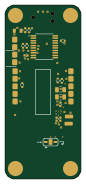
Haptic bracelet / satellite PCBA
20 × 46 mm26 parts4LNo license0
Pod-7-routed
17 × 35 mm24 parts4LNo license0
Pod-7
17 × 35 mm24 parts4LNo license0
Complete input routed
17 × 35 mm23 parts4LNo license0
Completed template
17 × 35 mm23 parts4LNo license0
Pod-6
17 × 35 mm23 parts4LNo license0
Similar boards
 ESP32
ESP32Open Book Abridged Edition
joeycastillo
85 × 115 mm65 parts2LCC-BY-SA-4.08.1k ESP32
ESP32Badge
atopile
56.3 × 39 mm239 parts4LMIT4.0k ESP32
ESP32Esp32 minimal
36.2 × 26.8 mm20 parts2LMIT4.0k ESP32
ESP32Racer
StuckAtPrototype
36 × 50.2 mm70 parts4LApache-2.03.8k ESP32
ESP32Controller
29 × 74 mm58 parts4LApache-2.03.8k ESP32
ESP32Bitaxe
skot
56.5 × 99.8 mm86 parts4LCERN-OHL-S-2.01.4k